


15. SERVO AMPLIFIER CONNECTION
15.6 Device Range that Can Be Set
15 - 17
SER
VO AMPLIFIER CONNECTION
15
15.6 Device Range that Can Be Set
The device ranges of controller that can be used for GOT
are as follows.
Note that the device ranges in the following tables are the
maximum values that can be set in GT Designer3.
The device specifications of controllers may differ
depending on the models, even though belonging to the
same series.
Please make the setting according to the specifications of
the controller actually used.
When a non-existent device or a device number outside
the range is set, other objects with correct device settings
may not be monitored.
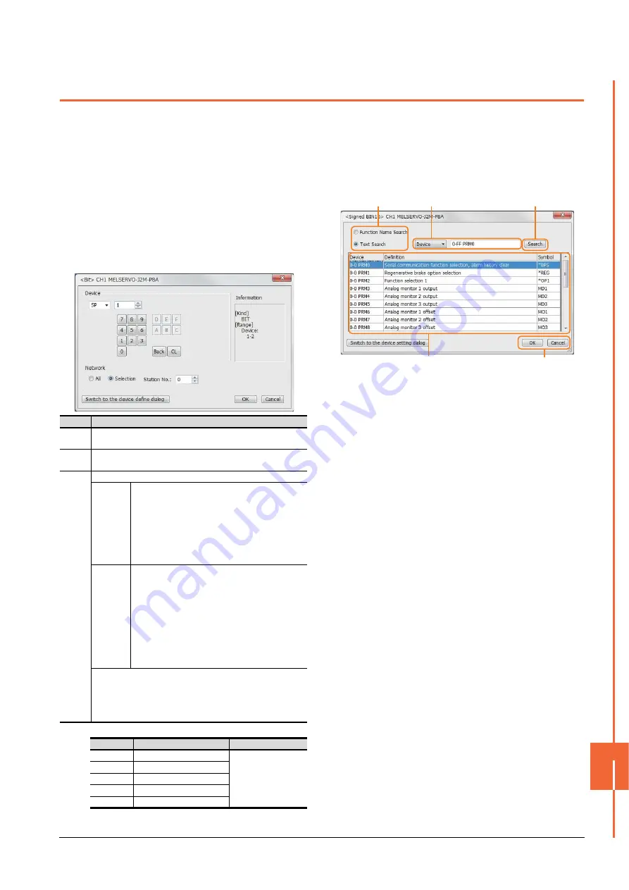
(1) Servo amplifier
For details of *1, refer to the following.
(a) Device Definition dialog box
When setting a device on the Device dialog box and
click the [Device Definition...] button, the
correspondence between the GOT virtual device for a
servo amplifier and the definition of the servo amplifier
is displayed.
The device can be searched with the servo definition or
other items on this dialog box to set a device.
1.
Select a key item for searching.
Function Name Search: Select this item when
searching a device with the function name.
Text Search: Select this item when searching a device
with the character string.
2.
Select and input a key item for searching.
3.
Click the [Search] button.
4.
The items that matches to the specified condition are
displayed.
The display contents are as follows.
Device
: The GOT virtual device for a servo
amplifier is displayed.
Definition : The definition of the servo amplifier is
displayed.
Symbol
: The abbreviated name for the servo
amplifier is displayed.
5.
Select a device to be set.
6.
Clicking the [OK] button reflects the device selected
by step 4 to the Device dialog box.
Item
Description
Device
Set the device name, device number, and bit number.
The bit number can be set only when specifying the bit of word device.
Informat
ion
Displays the device type and setting range which are selected in
[Device].
Network
Set the monitor target of the set device.
All
Select this item when writing data to all servo
amplifiers connected.
During a monitoring, the servo amplifier of Station
No. 0 is monitored.
When inputting data by Numerical Input, the data is
written to all servo amplifiers connected during
inputting; the servo amplifier of Station No. 0 is
monitored during other than inputting (displaying).
Selection
Select this item when monitoring the servo amplifier
of the Station No. specified.
After selecting, set station numbers of servo
amplifiers in the following range.
0 to 31:
The servo amplifier of the Station No. specified will
be monitored.
100 to 115:
Specify the Station No. of the servo amplifier to be
monitored with a GOT data register (GD).
*1
Switch
to the
device
define
dialog
Clicking the button displays the dialog box indicating the
correspondence between the GOT virtual device for a servo
amplifier and the definition of servo amplifier.
If selecting an item on the displayed dialog box, remember that
the servo amplifier definition is displayed in the text box below.
Station No.
GOT data register (GD)
Setting range
100
GD10
0 to 31
(If setting a value out
of the range above, a
timeout error occurs.)
101
GD11
:
:
114
GD24
115
GD25
1.
2.
6.
4. 5.
3.
Summary of Contents for GOT2000 Series
Page 2: ......
Page 62: ...1 38 1 PREPARATORY PROCEDURES FOR MONITORING 1 6 Checking for Normal Monitoring ...
Page 64: ......
Page 80: ...2 16 2 DEVICE RANGE THAT CAN BE SET 2 6 MELSEC WS ...
Page 246: ...7 26 7 COMPUTER LINK CONNECTION 7 6 Precautions ...
Page 252: ...8 6 8 BUS CONNECTION 8 1 Connectable Model List ...
Page 256: ...8 10 8 BUS CONNECTION 8 2 System Configuration ...
Page 288: ...8 42 8 BUS CONNECTION 8 4 Precautions ...
Page 324: ...9 36 9 MELSECNET H CONNECTION PLC TO PLC NETWORK MELSECNET 10 CONNECTION PLC TO PLC NETWORK ...
Page 416: ......
Page 510: ...15 46 15 SERVO AMPLIFIER CONNECTION 15 7 Precautions ...
Page 518: ...16 8 16 ROBOT CONTROLLER CONNECTION 16 6 Precautions ...
Page 540: ...17 22 17 CNC CONNECTION 17 7 Precautions ...
Page 541: ...MULTIPLE GOT CONNECTIONS 18 GOT MULTI DROP CONNECTION 18 1 ...
Page 542: ......
Page 567: ...MULTI CHANNEL FUNCTION 19 MULTI CHANNEL FUNCTION 19 1 ...
Page 568: ......
Page 599: ...FA TRANSPARENT FUNCTION 20 FA TRANSPARENT FUNCTION 20 1 ...
Page 600: ......
Page 668: ...20 68 20 FA TRANSPARENT FUNCTION 20 7 Precautions ...
Page 670: ...REVISIONS 2 ...
Page 673: ......


