


4 - 8
4. HOW TO MONITOR REDUNTANT SYSTEM
4.1 Connection to Remote I/O Station in MELSECNET/H Network System
4.1
Connection to Remote I/O Station in MELSECNET/
H Network System
4.1.1
Direct CPU connection (Direct CPU connection to the remote I/O station)
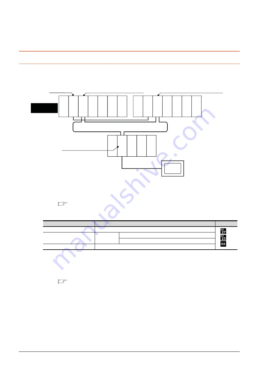
This section explains the direct CPU connection that connects the GOT to the remote I/O station of the MELSECNET/H
network system.
The following shows an example of connecting the GOT to the remote I/O station of the MELSECNET/H network system.
(1) Connection method
Connect the GOT to the RS-232 interface of the network module (QJ72LP25-25, QJ72LP25G, QJ72BR15) on
the remote I/O station of the MELSECNET/H network system.
For details, refer to the following.
(2) GT Designer3 setting
Set GT Designer3 as follows.
In this case, the GOT monitoring is performed by transient transmission of the MELSECNET/H network system.
Therefore, a longer time-lag occurs for displaying objects compared with directly monitoring the PLC CPU.
For displaying objects with a shorter time-lag, set the device for link devices B and W of the host station set in
the MELSECNET/H network and execute the cyclic transmission.
For details, refer to the following manual.
Q Corresponding MELSECNET/H Network System Reference Manual (Remote I/Q network)
(3) Monitoring target change when system switching occurs in a redundant system
When the system switching occurs, the multiplexed remote sub master station switched to the control system
takes over the master operation of MELSECNET/H.
Since the GOT monitors the master station, the monitoring target is automatically changed to the PLC CPU that
is operating as the master.
Setting item
Settings
Model
Controller Type
MELSEC-Q/QS, Q17nD/M/NC/DR, CRnD-700
Device setting (Network setting)
Other
NW No.: Network No. of MELSECNET/H remote I/O network
Station No.: 0 (Master station)
Q Redundant Setting
Do not set the item.
Monitor target
MELSECNET/H remote I/O network
CPU direct connection
GOT
Network No. 1, Station No. 0
(Multiplexed remote master station)
Control system
(System A)
Q25PRHCPU
QJ71LP21-25
QJ71BR1
1
QJ71E71-100
QJ61BT1
1N
Network No. 1, Station No. 1
(Multiplexed remote sub master station)
Standby system
(System B)
Q25PRHCPU
QJ71LP21-25
QJ71BR1
1
QJ71E71-100
QJ61BT1
1N
QJ72LP25-25
QJ71C24N
Network No. 1, Station No. 2
(Remote I/O station)
Empty
Empty
Power supply
module
Empty
Power supply
module
Empty
Power supply
module
Summary of Contents for GOT2000 Series
Page 2: ......
Page 62: ...1 38 1 PREPARATORY PROCEDURES FOR MONITORING 1 6 Checking for Normal Monitoring ...
Page 64: ......
Page 80: ...2 16 2 DEVICE RANGE THAT CAN BE SET 2 6 MELSEC WS ...
Page 246: ...7 26 7 COMPUTER LINK CONNECTION 7 6 Precautions ...
Page 252: ...8 6 8 BUS CONNECTION 8 1 Connectable Model List ...
Page 256: ...8 10 8 BUS CONNECTION 8 2 System Configuration ...
Page 288: ...8 42 8 BUS CONNECTION 8 4 Precautions ...
Page 324: ...9 36 9 MELSECNET H CONNECTION PLC TO PLC NETWORK MELSECNET 10 CONNECTION PLC TO PLC NETWORK ...
Page 416: ......
Page 510: ...15 46 15 SERVO AMPLIFIER CONNECTION 15 7 Precautions ...
Page 518: ...16 8 16 ROBOT CONTROLLER CONNECTION 16 6 Precautions ...
Page 540: ...17 22 17 CNC CONNECTION 17 7 Precautions ...
Page 541: ...MULTIPLE GOT CONNECTIONS 18 GOT MULTI DROP CONNECTION 18 1 ...
Page 542: ......
Page 567: ...MULTI CHANNEL FUNCTION 19 MULTI CHANNEL FUNCTION 19 1 ...
Page 568: ......
Page 599: ...FA TRANSPARENT FUNCTION 20 FA TRANSPARENT FUNCTION 20 1 ...
Page 600: ......
Page 668: ...20 68 20 FA TRANSPARENT FUNCTION 20 7 Precautions ...
Page 670: ...REVISIONS 2 ...
Page 673: ......


