526
FX
3U
/FX
3UC
Series Programmable Controllers
Programming Manual - Basic & Applied Instruction Edition
20 Positioning Control – FNC150 to FNC159
20.1 FNC150 – DSZR / Dog Search Zero Return
20.1
FNC150 – DSZR / Dog Search Zero Return
Outline
This instruction executes zero return, and aligns the mechanical position with a present value register inside
the PLC.
In addition, this instruction enables the following functions not supported by the ZRN (FNC156) instruction:
• DOG search function
• Zero return by the near-point (dog) signal and zero-phase signal
It is not possible, however, to count the zero-phase signal and then determine the zero point.
→
For explanation of the instruction, refer to the Positioning Control Edition.
→
For cautions on using special high speed output adapters, refer to the Positioning Control Edition.
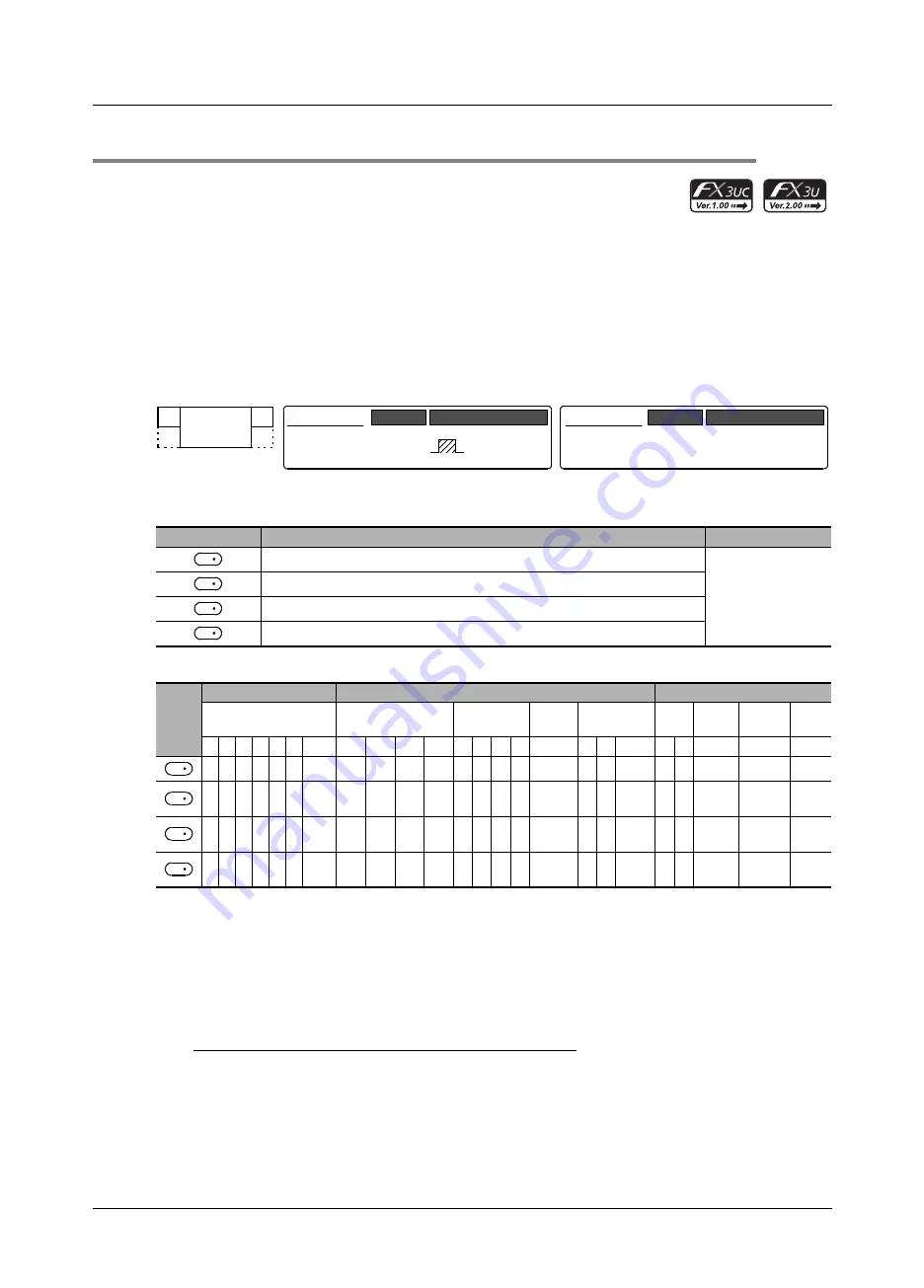
1. Instruction format
2. Set data
3. Applicable devices
S
1 : "D
.b" cannot be indexed with index registers (V and Z).
S
2 : Specify either one among X000 to X007.
S
3 : Specify a transistor output Y000, Y001, or Y002 in the main unit or Y000, Y001, Y002
*2
, or Y003
*2
in a
special high speed output adapter
*1
.
*1.
Special high speed output adapters cannot be connected to the FX
3UC
-32MT-LT.
*2.
For specifying Y002 or Y003 in a special high speed output adapter, the second special high
speed output adapter is required.
Points
• When using a relay output type FX
3U
PLC, a special high speed output adapter is required.
• Outputs of special high speed output adapters work as differential line drivers.
Operand type
Description
Data type
Device number inputting near-point signal (dog)
Bit
Input number inputting zero-phase signal
Device number outputting pulse
Device number to which rotation direction signal is output
Oper-
and
Type
Bit Devices
Word Devices
Others
System User
Digit Specification
System User
Special
Unit
Index
Con-
stant
Real
Number
Charac-
ter String
Pointer
X Y M T C S D
.b KnX KnY KnM KnS
T
C
D
R U
\G
V
Z Modify K
H
E
"
"
P
3 3 3 3
S
1
3
S
2
3
S
3
3
S
4
3 3
S
1
3
FNC 150
DSZR
−
Mnemonic
Operation Condition
16-bit Instruction
9 steps
DSZR
Mnemonic
Operation Condition
Continuous
Operation
32-bit Instruction
S
1
S
2
D
1
D
2
S
1
S
2
D
1
D
2


