background image

8 CF-ADP Applied Instructions Explanation

8.5 FNC 302 - FLWR / Data write

66

FX

3U

-CF-ADP User's Manual

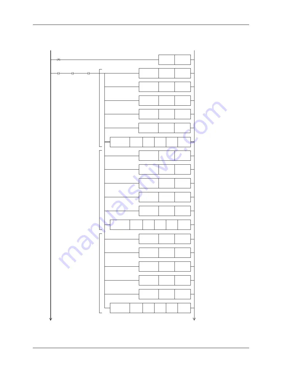
• Sequence program
It is assumed that M15 stores bit data, M16 stores bit data, and R200 stores 16-bit decimal data.
This program does not describe such values.

Specify the line position of the
writing destination.
The overwriting target is set to
Index 1.

D32

K2

D33

K3

FNC 12

 MOV

Specify the data column
position in the writing
destination.
The 2nd column is specified.

Data writing.
Only "mixed type" data is
specified.

Total number of written points.
"3 points" is specified.

M8425

CF card is

mounted

M0

M8424

CF-ADP

unit

ready

Specify the data writing type.
"Mixed type data" is specified.

FNC 12

 MOV

D31

K1

FNC302

FLWR

K5

D30

K0

FNC 12

 MOV

D100

D30

D20

K2

FNC 12

 MOV

M0

SET

X000

Specify the line position of the
writing destination.
The overwriting target is set to
Index 1.

D52

K2

D53

K1

FNC 12

 MOV

Specify the data column
position in the writing
destination.
The 2nd column is specified.
Number of written points.
"1 point" is specified.

FNC 12

 MOV

D51

K1

D50

K2

FNC 12

 MOV

FNC 12

 MOV

Specify the data writing type.
The 16-bit decimal type is
specified.

Data writing.
The data stored in the 2nd data
type is written.

FNC302

FLWR

K5

R200

D50

D20

K2

To next page

To next page

The data stored in the 2nd
data type is written.

Only "mixed type" data is
specified

D34

K0

FNC 12

 MOV

Writing destination.
The CF card is specified.

D54

K0

FNC 12

 MOV

Writing destination.
The CompactFlash

TM

 card is 

Specify the line position of the
writing destination.
The overwriting target is set to
Index 1.

D42

K2

D43

K2

FNC 12

 MOV

Specify the data column
position in the writing
destination.
The 2nd column is specified.

Number of written points.
"2 points" is specified.

FNC 12

 MOV

D41

K1

D40

K1

FNC 12

 MOV

FNC 12

 MOV

Specify the data writing type.
The bit type is specified.

Data writing.
The data stored in the 1st data
type is written.

FNC302

FLWR

K5

M15

D40

D20

K2

The data stored in the 1st
data type is written.

D44

K0

FNC 12

 MOV

Writing destination.
The CompactFlash

TM

 card is 

specified.

specified.

Summary of Contents for FX3U-CF-ADP

Page 1: ...FX3U CF ADP USER S MANUAL ...

Page 2: ......

Page 3: ...LC main unit detects an error during self diagnosis such as a watchdog timer error all outputs are turned off Also when an error that cannot be detected by the PLC main unit occurs in an input output control block output control may be disabled External circuits and mechanisms should be designed to ensure safe machinery operation in such cases 15 28 Reference Observe the following items Failure to...

Page 4: ... to the CF ADP power supply connector Loose connections may cause malfunctions When inserting a CompactFlashTM card into the FX3U CF ADP push it into the CF card slot until the EJECT button pops out Loose connections may cause malfunctions Before inserting removing a CompactFlashTM card into from the FX3U CF ADP set the CF card ACCESS switch to OFF and confirm that the BUFFER LED and ACCESS LED ar...

Page 5: ... or modify the PLC Doing so may cause fire equipment failures or malfunctions For repair contact your local Mitsubishi Electric distributor Turn off the power to the PLC before attaching or detaching the following devices Failure to do so may cause device failures or malfunctions Peripheral devices display modules expansion boards and special adapters I O extension units blocks FX Series terminal ...

Page 6: ... 4 ...

Page 7: ... and read it whenever necessary Always forward it to the end user 2009 MITSUBISHI ELECTRIC CORPORATION Manual number JY997D35401 Manual revision A Date 6 2009 This manual confers no industrial property rights or any rights of any other kind nor does it confer any patent licenses Mitsubishi Electric Corporation cannot be held responsible for any problems involving industrial property rights which m...

Page 8: ...ed to be incorporated in a device or system used in purposes related to human life Before using the product for special purposes such as nuclear power electric power aerospace medicine or passenger movement vehicles consult with Mitsubishi Electric This product has been manufactured under strict quality control However when installing the product where major accidents or losses could occur if the ...

Page 9: ...s 16 2 2 Power supply specification 16 2 3 Performance specification 16 2 4 CF card ACCESS switch specification 17 2 5 CompactFlashTM card specification 17 2 6 Applicable CompactFlashTM card 17 3 System Configuration 18 3 1 General configuration 18 3 2 Applicable PLC 19 3 2 1 Connectable PLC 19 3 2 2 Applicable versions of the programming tool 19 3 3 Connection with PLC 19 3 4 Assignment of channe...

Page 10: ... writing destination 39 7 1 6 File ID 40 7 1 7 FIFO file 41 7 2 Directory structure 42 7 3 Date time setting 42 7 4 General Rules for Applied Instructions 43 7 4 1 Expression and operation type of applied instructions 43 7 4 2 Programming using Instruction execution complete flag and Instruction execution abnormal end flag 44 8 CF ADP Applied Instructions Explanation 46 8 1 CF ADP Instructions typ...

Page 11: ...1 3 Error Code List and Action 102 10 2 Diagnostics on the PLC Main Unit 107 10 2 1 POWER POW LED on flashing off 107 10 2 2 BATT BAT LED on off 107 10 2 3 ERROR ERR LED on flashing off 108 Appendix A Related Devices 109 Appendix A 1 Related Device List 109 Appendix A 2 Details of related devices 110 Appendix A 2 1 Instruction execution complete M8029 110 Appendix A 2 2 Instruction execution abnor...

Page 12: ...er s Manual Table of Contents Appendix B Version Information 113 Appendix B 1 Version information 113 Appendix B 1 1 Version check method 113 Appendix B 1 2 Version upgrade history 113 Warranty 115 Revised History 116 ...

Page 13: ...in unit please refer to either the FX series product catalog or consult with your nearest Mitsubishi product provider Requirement for Compliance with EMC directive The following products have shown compliance through direct testing of the identified standards below and design analysis through the creation of a technical construction file to the European Directive for Electromagnetic Compatibility ...

Page 14: ...rammable logic controller Control cabinet The control cabinet must be conductive Ground the control cabinet with the thickest possible grounding cable To ensure that there is electric contact between the control cabinet and its door connect the cabinet and its doors with thick wires In order to suppress the leakage of radio waves the control cabinet structure must have minimal openings Also wrap t...

Page 15: ...1601 Describes FX3UC 32MT LT 2 specification for I O wiring and installation extracted from the FX3UC User s Manual Hardware Edition For details refer to FX3UC Series User s Manual Hardware Edition Supplied Manual FX3UC 32MT LT Hardware Manual Only Japanese document JY997D12701 Describes FX3UC 32MT LT specification for I O wiring and installation extracted from the FX3UC User s Manual Hardware Edi...

Page 16: ... special function unit and special function block The number of connectable units however depends on the type of main unit To check the number of connectable units refer to the User s Manual Hardware Edition of the main unit to be used for your system Special function unit Generic name for special function unit Special function block Generic name for special function block The number of connectabl...

Page 17: ... Edition FX3UC Series User s Manual Hardware Edition Programming manual FX3G FX3U FX3UC Series Programming Manual Basic and Applied Instructions Edition Communication control Edition FX Series User s Manual Data Communication Edition Analog control Edition FX3G FX3U FX3UC Series User s Manual Analog Control Edition Positioning control Edition FX3G FX3U FX3UC Series User s Manual Positioning Contro...

Page 18: ...ly This area shows the title of the chapter and the title of the section for the current page The right side of each page indexes the chapter number for the page currently opened This area shows the manual title for the current page The mark indicates a reference destination and reference manual Shows the reference Indexes the chapter number Shows the title of the chapter and the title of the sect...

Page 19: ...function Data can be saved in a specified file stored in the CompactFlashTM card Data can be read from the CompactFlashTM card For details on the functions refer to Chapter 6 1 2 External Dimensions and Part Names 1 DIN rail mounting groove DIN rail DIN46277 35mm 1 38 width 9 CF card slot 2 Nameplate 10 Special adapter connector 3 Special adapter slide lock 11 EJECT button 4 Special adapter connec...

Page 20: ... write error CompactFlashTM card error etc has occurred FULL Red OFF The CompactFlashTM card has free space Flicker The free space in the CompactFlashTM card is 20 or less of the full capacity ON The CompactFlashTM card has no free space The free space in the CompactFlashTM card is 1 or less of the full capacity ACCESS Red OFF CompactFlashTM card not accessed ON CompactFlashTM card being accessed ...

Page 21: ...se to the PLC and result in PLC failure machine damage or other accident 1 Do not bundle the control line together with or lay it close to the main circuit or power line As a guideline lay the control line at least 100mm 3 94 or more away from the main circuit or power line Noise may cause malfunctions 2 Ground the shield wire or shield of a shielded cable Do not use common grounding with heavy el...

Page 22: ...fication Adapter driving power supply Power supply voltage 24V DC 20 15 Ripple p p within 5 Permitted instantaneous power failure time Operation continues when the instantaneous power failure is shorter than 1ms Current consumption 130mA Connect a 24V DC power supply to the power supply connector Interface driving power supply 50mA 5V DC 5V DC power is supplied internally from the main unit Item S...

Page 23: ...fe of a CompactFlashTM card is expired when data is written to it a specified number of times Generally at the end of the operational life the CompactFlashTM card has reduced capabilities Please use it ensuring sufficient availability Setting item Description ON Access to the CompactFlashTM card enabled OFF 1 Access to the CompactFlashTM card disabled Item Specification Operating ambient humidity ...

Page 24: ...M card GT05 MEM 128MC GT05 MEM 256MC GT05 MEM 512MC GT05 MEM 1GC GT05 MEM 2GC CompactFlashTM cards available for the CF ADP Memory card adapter GT05 MEM ADP The memory card adapter is used to convert a CF card into a memory card Type II PC software GX Developer PLC programming software PC USB cable FX USB AW Cable with RS 422 USB converter between a FX PLC and PC RS 232C cable F2 232CAB 1 PC conne...

Page 25: ...or the CF ADP of the FX3U FX3UC Series PLC Caution If a programming tool with the wrong version number is used programming will not be possible 3 3 Connection with PLC The CF ADP connects with a FX3U FX3UC PLC via an interface connector Only one CF ADP unit can be connected to the FX3U FX3UC PLC An expansion board is required to connect the CF ADP with the FX3U FX3UC 32MT LT PLCs For details of as...

Page 26: ... CF ADP The channel number is assigned as shown below 1 FX3U FX3UC 32MT LT 2 PLC When using channel 1 ch1 When using channel 2 ch2 Caution on using the CF ADP The CF ADP is handled in the same way as communication expansion boards and communication special adapters and occupies one communication channel Other special adapters Main unit FX3U CF ADP FX3U FX3UC 32MT LT 2 Main unit FX3U CNV BD CF ADP ...

Page 27: ...10 Troubleshooting 2 FX3UC D DSS PLC When using channel 1 ch1 When using channel 2 ch2 Caution on using the CF ADP The CF ADP is handled in the same way as communication special adapters and occupies one communication channel FX3UC D DSS Main unit CF ADP Communication special adapter ch2 ch1 Analog special adapter Analog special adapter FX3UC D DSS Main unit Communication special adapter CF ADP ch...

Page 28: ...mounting surface is rough undue force will be applied to the PC board thereby causing nonconformities When drilling screw holes or wiring make sure that cutting and wiring debris do not enter the ventilation slits Failure to do so may cause fire equipment failures or malfunctions Be sure to remove the dust proof sheet from the PLC s ventilation port when installation work is completed Failure to d...

Page 29: ...nual Refer to the FX3U Hardware Edition Refer to the FX3UC Hardware Edition 1 Remove the special adapter connector cover A in the figure on the right from the expansion board It is assumed that an expansion board has been installed in advance For the expansion board installation method refer to the respective PLC manual Refer to the FX3U Hardware Edition Refer to the FX3UC Hardware Edition 2 Slide...

Page 30: ...e respective PLC manual Refer to the FX3U Hardware Edition Refer to the FX3UC Hardware Edition 1 Push out all DIN rail mounting hooks A in the figure on the right It is assumed that the CF ADP has been connected in advance For the CF ADP connection method refer to the following Refer to Section 4 1 2 Fit the upper edge B in the figure on the right of the DIN rail mounting groove onto the DIN rail ...

Page 31: ...al Refer to the FX3U Hardware Edition 1 Create mounting holes in the mounting surface according to the external dimensions diagram 2 Fit the CF ADP to the mounting holes and tighten with M4 screws A in the figure on the right Also fit the main unit to the mounting holes and tighten with M4 screws For the main unit connection method refer to the following Refer to the FX3U Hardware Edition It is as...

Page 32: ...S switch to OFF A in the figure on the right in the CF ADP Confirm that the POWER LED is lit 2 Open the CF card cover Insert the CompactFlashTM card into the CF card slot with the front side side B in the figure on the right facing the right side of the CF ADP until the EJECT button side C in the figure on the right pops out 3 Confirm that the CF card ACCESS LED is lit or flickers and turns OFF an...

Page 33: ...figure on the right and make sure that the CF card ACCESS LED and BUFFER LED B in the figure on the right both turn off When the CF card ACCESS LED turns off the CompactFlashTM card can be removed even when the CF ADP is powering on When the CF card ACCESS LED is lit or flickering do not removing the CompactFlash card or power off the CF ADP Doing so may cause data corruption or malfunction 2 Open...

Page 34: ...ower off the CF ADP Failure to do so may cause CompactFlashTM card failures or malfunctions If the power is turned OFF while the CompactFlashTM card is being accessed ACCESS LED is lit or flickering the buffered data is erased Also files or CompactFlashTM card itself may be damaged Do not turn the power OFF while the ACCESS LED is lit or flickering Do not apply excessive pressure to the power supp...

Page 35: ...ng wiring material and connector type STARTUP AND MAINTENANCE PRECAUTIONS Do not disassemble or modify the PLC Doing so may cause fire equipment failures or malfunctions For repair contact your local Mitsubishi Electric distributor Turn off the power to the PLC before attaching or detaching the following devices Failure to do so may cause device failures or malfunctions Peripheral devices display ...

Page 36: ...hould be 100 or less Independent grounding should be established whenever possible Independent grounding should be performed for best results When independent grounding is not configured perform shared grounding as shown in the following figure For details refer to the respective PLC manual Refer to the FX3U Hardware Edition Refer to the FX3UC Hardware Edition The grounding point should be close t...

Page 37: ... LED A in the figure on the right and BUFFER LED B in the figure on the right are completely OFF 3 Turn the power of the CF ADP OFF 5 4 2 Power OFF procedure using the applied instruction for the CF ADP 1 Execute the FLCMD instruction to unmount the CompactFlashTM card 2 Confirm that the FLCMD instruction is completed normally 3 Turn the power of the CF ADP OFF 5 4 3 Caution on power OFF If the po...

Page 38: ... CF ADP receives and supplies power through the built in dedicated power connector 5 5 1 Connection removal of the power supply cable Connection Connect the power supply cable after confirming the connector direction Removal Squeeze the power cable connector at a and disconnect it in the direction of the arrow Press here a ...

Page 39: ... card Writing bit data word data double word data floating point data and character string data to a specified file stored in the CompactFlashTM card Data can be written to the CompactFlashTM card using the following two methods Data is directly written to the CompactFlashTM card without using the internal buffer Up to 254 data points can be written to one line Data is collected in the internal bu...

Page 40: ...codes of the CF ADP Data capacity of the CompactFlashTM card Unit kB 1 MB 1024 kB 1 GB 1024 MB 1 048 576 kB Capacity less than 1 kB is regarded as 1 kB Used space of the CompactFlashTM card Unit kB 1 MB 1024 kB 1 GB 1024 MB 1 048 576 kB Capacity less than 1 kB is regarded as 1 kB Free space of the CompactFlashTM card Unit kB 1 MB 1024 kB 1 GB 1024 MB 1 048 576 kB Capacity less than 1 kB is regarde...

Page 41: ...F ADP and by the user 7 1 1 Files created by the CF ADP Files in the csv format created by the CF ADP are as follows The CF ADP can read and write files whose data is separated by comma and line feed by CR LF One line can store up to 254 data points For characters available in files refer to Subsection 7 1 3 CSV file DATE TIME Index CR Data name Data name Data name Data name LF Year Month Day Hour...

Page 42: ...truction match the data type for each saved data point Specify the same data type If the data types do not agree data cannot be read normally No Contents of data Description Remark 1 Index DATE TIME When the file name is added the Index date and time are added automatically 2 Data name Character string consisting of up to 32 half width full width characters Refer to Subsection 7 1 3 3 Index 6 digi...

Page 43: ...using the following symbols confirm the application software specifications Apostrophe caret backslash slash at mark and equal sign 6 The expression of date and time depends on the setting of the region Check the used method 7 When data is read in floating point format the data point is converted from the head to the position which can be read as a numeric value if characters outside the floating ...

Page 44: ... count is different Contents of data Used characters Number of bytes Symbol Remark Index 6 digits expressed in a decimal number from 1 to 32767 Space is put in for unused digits Plus signs are used in some systems 6 bytes Decimal 6 digits 1 character 1 byte Comma year Month Day Hour Minute Seconds None 0 byte a The expression of date and time depends on the setting of the region Check the used met...

Page 45: ... from the buffer inside the CF ADP to the CompactFlashTM card is counted as a data write to the CompactFlashTM card However attention is required because data is cleared in the following cases Data is cleared at the following times and data is written from the internal buffer inside the CF ADP to the CompactFlashTM card at the following times Times when the internal buffer inside the CF ADP is cle...

Page 46: ...er should use the file ID for specifying the file instead of using the file name File creation program ID table image D11 K D12 K The file is created D0 TEST_01 FNC209 MOV M8405 CF card is mounted M0 M8404 CF ADP unit ready File name The file name is set to TEST_01 CSV D10 K FNC 12 MOV D13 K K1 D10 D0 FNC300 FLCRT K1 M0 SET X000 File ID File name FNC 12 MOV FNC 12 MOV FNC 12 MOV M0 RST M8329 Abnor...

Page 47: ...n created files exceed the CompactFlashTM card capacity specified CompactFlashTM card use ratio The CF ADP creates files whose name consists of a consecutive number in ascending order starting from FILE0000 CSV within the CompactFlashTM card capacity When created files reach the CompactFlashTM card capacity the CF ADP deletes the oldest existing file and creates a new file FIFO file creation Cauti...

Page 48: ...ke sure to set the clock data in the main unit before using the CF ADP The available clock data range is from 00 00 00 on January 1 2008 to 23 59 59 on December 31 2079 If the user sets the date and time outside this range 00 00 00 on January 1 2008 is actually set instead For the clock data setting method in the main unit refer to the following manual Refer to the programming manual Root FX3U_CF ...

Page 49: ...e two or more destinations the modified destinations will become and so on m n The operands not corresponding to source and destination are indicated as m and n If the device number can be indexed by index registers and if there are two or more operands the modified operands will become m1 m2 n1 n2 and so on Regarding program steps the instruction area for each applied instruction is 1 step The op...

Page 50: ...n refer to the example shown on the next page Bad example The M8029 will function as the instruction execution complete flag of the lower DSW instruction The M8029 will function as the instruction execution complete flag of the upper FLSTRD instruction The M8029 will function as the instruction execution complete flag of the lower FLSTRD instruction RST M0 FNC 22 MUL D0 K10 D20 M8000 X10 Y10 D0 Co...

Page 51: ...to use the Instruction execution complete flag M8029 or Instruction execution abnormal end flag M8329 at a point other than just below the instruction turn on or off another bit device just below the instruction and use the contact as the command contact M8000 FNC 72 DSW X10 Y10 D0 K1 FNC 22 MUL D0 K10 D20 M8029 Completion of instruction execution M0 FNC300 FLCRT K1 D0 D10 M8029 Completion of inst...

Page 52: ...gramming For processing for the CF ADP keep ON the command input for an applied instruction for the CF ADP ON until processing has been completed Make such a program that the command input is set to OFF using the instruction executing complete flag M8029 after all processing for the CF ADP are finished Program Example 3 Instruction execution complete flag M8029 When processing for the CF ADP has b...

Page 53: ...pplication command for the CF ADP with the smaller step number in a program and completing instructions execution the next application instructions for the CF ADP is executed 3 Caution on writing during RUN CF ADP instruction cannot be written to during RUN mode When the user writes an applied instruction for the CF ADP during RUN mode execution of the instruction is canceled 4 Number of times dat...

Page 54: ...ly each file name saved in the CompactFlashTM card is associated with the file ID and controlled by the file ID table If a file having the specified file name already exists and is registered in the file ID table the PLC finishes the FLCRT instruction without executing any processing If a file having the specified name already exists but is not registered in the file ID table the PLC only register...

Page 55: ...ymbols _ The extension is fixed to CSV Character string File creation parameter Time stamp setting Set whether or not the time stamp is added to the file Specify the format when adding the time stamp K0 None NULL K1 yyyy mm dd hh mm ss K2 yy mm dd hh mm ss K3 dd mm yyyy hh mm ss K4 dd mm yy hh mm ss K5 mm dd yyyy hh mm ss K6 mm dd yy hh mm ss K7 hh mm ss 16 bit binary 1 Data type Set the data type...

Page 56: ...ON The time stamp setting data type maximum Index value and processing when the maximum Index value is reached are as shown below The channel number 1 is used Time stamp setting The time stamp format yyyy mm dd hh mm ss is set D11 K2 D12 K1000 FNC 12 MOV Data type setting The file type is set to 16 bit decimal Processing when the maximum line value is reached The processing is set to Stops executi...

Page 57: ...hod or format type using When is K 1 H0FFFF or K0 to K63 specify the deletion method K0 The FLDEL instruction deletes the specified file K1 The FLDEL instruction deletes the association between the file name and the file ID but does not delete the file itself However when the file ID specified in is 0 the FLDEL instruction deletes the file without regard to the setting of When is K512 H200 specify...

Page 58: ... FLDEL instruction deletes a file associated with the specified file ID K512 H200 The FLDEL instruction formats the CompactFlashTM card 16 bit binary When is K 1 H0FFFF or K0 to K63 Specify the deletion method K0 The FLDEL instruction deletes the specified file K1 The FLDEL instruction deletes the association between the file name and the file ID but does not delete the file itself However when th...

Page 59: ...on 4 Installation 5 Wiring 6 Functions 7 Before Programming8 CF ADP Applied Instructions Explanation 9 Program Examples 10 Troubleshooting 3 Program Example 3 This program formats the CompactFlashTM card in the FAT 16 format when X000 turns ON Channel number 1 is used X000 M0 SET FNC301 FLDEL H200 H100 K1 M0 M8029 Execution completion M0 RST M8329 Abnormal end M0 RST ...

Page 60: ... Refer to Subsection 8 5 1 16 bit binary Position after data writing Refer to Subsection 8 5 1 16 bit binary n Used channel number contents of setting K1 ch1 K2 ch2 16 bit binary Operand Type Bit Devices Word Devices Others System User Digit Specification System User Special Unit Index Con stant Real Number Charac ter String Pointer X Y M T C S D b KnX KnY KnM KnS T C D R U G V Z Modify K H E P n ...

Page 61: ...verwritten Line position after writing Written line position if data is not written to the final column position of the specified line position Line position next to the written line position if data is written to the final column position of the line Column position after writing Column position next to the final written data point K1 if data is written to the final data point in the line K1 if d...

Page 62: ...e data type is set to anything other than bit type When a word device is specified in and the data type is set to bit the FLWR instruction acquires data to be written from the least significant bit of the specified device 8 When is K7 or K8 00H which indicates the end of the string must be added to the end of the character string Setting items Description Data Type File ID K0 to K63 16 bit binary ...

Page 63: ...Index 3 in the following file The writing destination is the CompactFlashTM card D0 stores the line position after writing and D1 stores the column position after writing Channel 1 is used in this program For details on sequence programs refer to next page Content of file Instruction name FLWR S2 K K Data type specification Line position n Source data S2 Data write parameter S3 S1 File ID Line pos...

Page 64: ...The head position is specified Number of written points 5 points is specified M8405 CF card is mounted M0 M8404 CF ADP unit ready Specify the data writing type Decimal 16 bit type is specified FNC 12 MOV D21 K 1 D20 K2 FNC 12 MOV FNC 12 MOV M0 SET X000 D24 K0 FNC 12 MOV Writing destination The CompactFlashTM card is specified D100 D8418 D101 D8417 FNC 12 MOV The error code is stored The error code...

Page 65: ... position next to the written line position and the column position after writing is K1 Program Example Explanation of operation When X000 turns ON the decimal 16 bit data stored in D10 and D11 overwrites the Index 2 in the following file The writing destination is the CompactFlashTM card D0 stores the line position after writing and D1 stores the column position after writing Channel 1 is used in...

Page 66: ...writing destination The 3rd column is specified Number of written points 2 points is specified M8405 CF card is mounted M0 M8404 CF ADP unit ready Specify the data writing type Decimal 16 bit type is specified FNC 12 MOV D21 K2 D20 K2 FNC 12 MOV FNC 12 MOV M0 SET X000 D24 K0 FNC 12 MOV Writing destination The CompactFlashTM card is specified D100 D8418 D101 D8417 FNC 12 MOV The error code is store...

Page 67: ...Line position after writing D Line position after writing D Line position after writing D Used channel number n K or K 1 K or K 1 K r s t u Device 1 K Device a Instruction name K Specify a matching file ID Specify a matching device n Specify a matching channel number Source data S2 Data write parameter S3 S1 File ID Used channel number n Instruction name K Specify a matching file ID Specify a matc...

Page 68: ...101 and D100 32 bit hexadecimal type data stored in Y010 bit type data stored in Y011 bit type data stored in R100 16 bit decimal type and data stored in R101 16 bit decimal type are written respectively to Index 3 additionally in the following file The writing destination is the CompactFlashTM card D20 stores the line position after writing and D21 stores the column position after writing Channel...

Page 69: ...ion of the writing destination Additional writing is specified D52 K 1 D53 K2 FNC 12 MOV Specify the data column position in the writing destination Additional writing is specified Number of written points 2 points is specified FNC 12 MOV D51 K 1 D50 K1 FNC 12 MOV FNC 12 MOV Specify the data writing type The bit type is specified Data writing The data stored in the 2nd data type is written FNC302 ...

Page 70: ...pecify the data column position in the writing destination Additional writing is specified Writing destination The CompactFlashTM card is Total number of written points 1 point is specified FNC 12 MOV D61 K 1 D60 K2 FNC 12 MOV FNC 12 MOV FNC302 FLWR K5 D64 K0 FNC 12 MOV R100 D60 D20 K2 Specify the data writing type The 16 bit decimal type is specified Data writing The data stored in the 3rd device...

Page 71: ... after writing is the line position next to the written line position and the column position after writing is K1 Program Example Explanation of operation When X000 turns ON the data stored in M15 bit type data stored in M16 bit type and data stored in R200 16 bit decimal type overwrites respectively the Index 1 in the following file The writing destination is the CompactFlashTM card D20 stores th...

Page 72: ...he writing destination The 2nd column is specified Number of written points 1 point is specified FNC 12 MOV D51 K1 D50 K2 FNC 12 MOV FNC 12 MOV Specify the data writing type The 16 bit decimal type is specified Data writing The data stored in the 2nd data type is written FNC302 FLWR K5 R200 D50 D20 K2 To next page To next page The data stored in the 2nd data type is written Only mixed type data is...

Page 73: ...guration 4 Installation 5 Wiring 6 Functions 7 Before Programming8 CF ADP Applied Instructions Explanation 9 Program Examples 10 Troubleshooting D100 D8438 D101 D8437 FNC 12 MOV The error code is stored The error code details are stored FNC 12 MOV M0 RST M0 RST M8029 M8329 From previous page From previous page Execution completion Abnormal end ...

Page 74: ... 6 3 Operand Type Description Data Type File ID Refer to Subsection 8 6 1 16 bit binary Data read parameter Refer to Subsection 8 6 1 16 bit binary Device which stores the read data Refer to Subsection 8 6 1 Number of data points existing in the specified line Refer to Subsection 8 6 1 16 bit binary n Used channel number contents of setting K1 ch1 K2 ch2 16 bit binary Operand Type Bit Devices Word...

Page 75: ...es which store the read data is insufficient the FLRD instruction does not read data from the CF ADP An error occurs 5 When the data type is a character string the character string length is unknown The PLC stores as much read data as possible When reading is not completed even after the final device is reached an error occurs Setting items Description Data Type File ID K0 to K63 16 bit binary Dat...

Page 76: ...F Data5 Data4 Data3 Data2 111 1 2 3 2009 9 9 23 59 00 222 333 444 555 CR LF 1111 2222 3333 4444 5555 111 222 333 444 555 2009 9 9 23 59 02 2009 9 9 23 59 04 CR LF CR LF Device which stores the read data Value Read data Total number of data R1000 K 444 R1001 K555 D200 K5 File ID K10 The data name is already written After the FLRD instruction is executed Line position from which data is read Index 3...

Page 77: ...g FLDR instructions in accordance with each transferred data point using the MOV instruction etc At this time do not use a pulse type instruction Command input S1 S2 D1 D2 Instruction name Data read parameter File ID Read data Total number of data Used channel number FLRD Only mixed type data n K0 Specify mixed type data S2 S2 1 S2 2 S2 3 K K K r s t u Total points K Device n Device a S1 S2 D1 D2 ...

Page 78: ...10 K5 M201 K1 ON D200 K 44 Line position from which data is read Index 2 is specified D22 K1 D23 K4 FNC 12 MOV Column position from which data is read The 1st column is specified Data reading Only mixed type data is specified Total number of read points 4 points is specified M8425 CF card is mounted M0 M8424 CF ADP unit ready Specify the data reading type Mixed type data is specified FNC 12 MOV D2...

Page 79: ...ata stored in the 2nd data type is read Number of read data points 2 points is specified FNC 12 MOV D41 K2 FNC303 FLRD K5 D40 K1 FNC 12 MOV D40 M200 D10 K2 FNC 12 MOV Line position from which data is read The 1st column is specified D52 K1 D53 K1 FNC 12 MOV Column position from which data is read The 1st column is specified Data reading The data stored in the 3rd data type is read Number of read d...

Page 80: ...he FLCMD instruction sets the CompactFlashTM card to the mounted status if it is in the unmounted status When is K512 H200 the FLCMD instruction sets the CompactFlashTM card to the unmounted status if it is in the mounted status When is K1280 H500 the FLCMD instruction clears error codes stored in the CF ADP For details refer to Subsection 8 7 1 Operand Type Description Data Type Instruction for o...

Page 81: ...0 turns ON the CompactFlashTM card is set to the mounted status Channel number 1 is used 3 Program Example 3 When X000 turns ON error codes stored in the CF ADP are cleared Channel number 1 is used Setting items Description Data Type Contents of instruction for operation K 1 Forcibly writes all buffered data to the CompactFlashTM card K0 to K63 Forcibly writes the buffered data of the specified fi...

Page 82: ... of the CF ADP When is K1024 H400 the FLSTRD instruction reads the error information error flag for errors having occurred in the CF ADP When is K1280 H500 the FLSTRD instruction reads error codes and error code details Up to 5 of the latest error codes and error code details can be stored For details refer to Subsection 8 8 1 Operand Type Description Data Type Contents of status to be read Refer ...

Page 83: ...line position of each file K256 H100 File IDs stored in the CompactFlashTM card K512 H200 Capacity of the CompactFlashTM card K768 H300 Version of the CF ADP K1024 H400 Error information error flag K1280 H500 Error codes 16 bit binary Head device to which the read status is written The number of data points stored in varies depending on the contents of the read status 16 bit binary n Channel numbe...

Page 84: ...e final line position of a file whose ID is 1 and D101 stores the final digit position Channel number 1 is used Setting items Description Stores the version of CF ADP Example K100 Ver 1 00 Setting items Description Error detection signal b0 The CompactFlashTM card is not mounted b1 The CompactFlashTM card is full b2 An error has occurred in the CF ADP b3 CF ADP H W error b4 CompactFlashTM card err...

Page 85: ... is 1 exists Channel number 1 is used 3 Program Example 3 When X000 turns ON the FLSTRD instruction reads the capacity of the CompactFlashTM card D101 and D100 store the data capacity of the CompactFlashTM card D103 and D102 store the used space of the CompactFlashTM card and D105 and D104 store the free space of the CompactFlashTM card Channel number 1 is used X000 M0 SET M0 FNC305 FLSTRD D0 K1 H...

Page 86: ...n executing Remains ON while an instruction for the CF ADP is being executed R M8404 M8424 CF ADP unit ready Remains ON when the CF ADP is ready for receiving commands R M8405 M8425 CF card mount status ON CompactFlashTM card mounted status OFF CompactFlashTM card unmounted status R M8410 M8430 CF ADP status renewal stop Stops communication executed by the system to update the status of special da...

Page 87: ...he CF ADP are read For details refer to Section 9 4 STARTUP AND MAINTENANCE PRECAUTIONS Make sure to connect the battery correctly Do not charge disassemble heat short circuit or expose the battery to fire Doing so may rupture or ignite it Do not touch any terminal while the PLC s power is on Doing so may cause electric shock or malfunctions Before modifying or disrupting the program in operation ...

Page 88: ...0000 710000 0 2009 9 9 23 59 00 0 2009 9 9 23 59 28 0 0 0 0 100000 300000 500000 1 10 100 1000 10000 2 20 200 2000 20000 3 30 300 3000 30000 4 40 400 4000 40000 5 50 500 5000 50000 6 60 600 6000 60000 7 70 700 7000 70000 8 80 800 8000 80000 9 90 900 9000 90000 9 90 900 9000 90000 8 80 800 8000 80000 7 70 700 7000 70000 6 60 600 6000 60000 5 50 500 5000 50000 4 40 400 4000 40000 3 30 300 3000 30000...

Page 89: ...ine position is reached D20 Specify the data writing type D21 Specify the line position of the writing destination D22 Specify the data column position in the writing destination D23 Number of written data points D24 Writing destination Internal buffer inside the CF ADP CompactFlashTM card D28 Executes forcible writing of buffered data to the CompactFlashTM card after data is written to the buffer...

Page 90: ...e error code details are stored M20 RST 32 bit decimal type file is created successfully Remains ON while data is being written to the 32 bit decimal type file Turns ON when data is written successfully to the 32 bit decimal type file X001 M2 SET M22 RST Remains ON while data is being read from the 32 bit decimal type file Turns ON when data is read successfully from the 32 bit decimal type file X...

Page 91: ... file name is set to DWORD_01 FNC 12 MOV D10 K1 FNC 12 MOV D13 K0 FNC 12 MOV K1 D10 D0 FNC305 FLCRT K1 Remains ON while a new 32 bit decimal type file is being created D102 D8418 D103 D8417 FNC 12 MOV The error code is stored Remains ON while a new 32 bit decimal type file is being created The error code details are stored FNC 12 MOV M61 SET M60 RST M60 RST M8029 M8329 D200 Device1 FNC209 MOV M840...

Page 92: ...reated successfully or already exists Specify the line position of the writing destination D22 K 1 D23 K10 FNC 12 MOV Specify the data column position in the writing destination Writing destination Data writing Number of written data points M8405 CF card is mounted M1 M8404 CF ADP unit ready Remains ON while data is being written to the 32 bit decimal type file Specify the data writing type FNC 12...

Page 93: ... D28 FNC 230 LD K10 From previous page From previous page To next page To next page Specify the line position from which data is read Final line D42 K1 D43 K10 FNC 12 MOV Column position from which data is read Data reading Number of read data points M8405 CF card is mounted M2 M8404 CF ADP unit ready Remains ON while data is being read from the 32 bit decimal type file Specify the data reading ty...

Page 94: ...l type file is being deleted D112 D8418 D113 D8417 FNC 12 MOV The error code is stored Remains ON while the 32 bit decimal type file is being deleted Turns ON when the 32 bit decimal type file is deleted successfully The error code details are stored FNC 12 MOV M23 SET M3 RST M3 RST M8029 M8329 K1 K0 K1 FNC301 FLDEL END From previous page From previous page The 32 bit decimal type file is deleted ...

Page 95: ...ssignments Device No Contents of operation X004 Creates a mixed type file and writes data names X005 Writes data to the mixed type file X006 Reads data from the mixed type file 1 10 2000000 1 11E 00 111E AAAA111E ABCDEFGHIJ 0 20 3000000 1 12E 00 111F BBBB111F ABCDEFGHI 1 30 4000000 1 13E 00 222A BBBB222A ABCDEFGH 0 40 5000000 1 14E 00 222B BBBB222B ABCDEFG 1 50 6000000 1 15E 00 222C BBBB222C ABCDE...

Page 96: ...e D41 Specify the line position from which data is read D42 Column position from which data is read D43 Number of read data points D50 Number of data points existing in the specified line D114 D115 Error code error code details when existence of a file whose file ID is 1 is confirmed D116 D117 Error code error code details when a mixed type file is created D118 D119 Error code error code details w...

Page 97: ...ng created Remains ON while a mixed type file is being created Remains ON while a new mixed type file is being created The error code details are stored M24 RST Turns ON when a mixed type file is created successfully or already exists Remains ON while data is being written to the mixed type file Turns ON when data is written successfully to the mixed type file X005 M6 SET M26 RST Remains ON while ...

Page 98: ...le is being created D116 D8418 D117 D8417 FNC 12 MOV The error code is stored Remains ON while a new mixed type file is being created Remains ON while data names of the mixed type are being written The error code details are stored FNC 12 MOV M63 SET M62 RST M62 RST M8029 M8329 D300 Bit FNC209 MOV M8405 CF card is mounted M63 M8404 CF ADP unit ready Remains ON while data names of the mixed type ar...

Page 99: ...xed type are being written Remains ON while a mixed type file is being created The error code details are stored FNC 12 MOV M24 SET M63 RST M63 RST M8029 M8329 D20 K8 FNC 12 MOV D300 D20 D30 K1 Specify the line position of the writing destination D22 K 1 D23 K7 FNC 12 MOV Specify the data column position in the writing destination Writing destination Mixed type data is written Number of written da...

Page 100: ...pe D23 K1 FNC 12 MOV FNC302 FLWR K0 D20 K5 FNC 12 MOV R30 D20 D30 K1 Number of written data points Data writing Specify the data writing type D23 K1 FNC 12 MOV FNC302 FLWR K0 D20 K6 FNC 12 MOV R40 D20 D30 K1 Number of written data points Data writing Specify the data writing type D23 K1 FNC 12 MOV FNC302 FLWR K0 D20 K7 FNC 12 MOV R50 D20 D30 K1 M8405 CF card is mounted M5 M8404 CF ADP unit ready R...

Page 101: ... MOV D41 K1 FNC 21 SUB FNC303 FLRD K0 D40 K0 FNC 12 MOV D40 M400 D50 K1 D30 D40 K1 FNC 12 MOV D43 K1 FNC 12 MOV Number of read data points Data reading FNC303 FLRD K0 D40 M400 D50 K1 Specify the data reading type D40 K2 FNC 12 MOV D43 K1 FNC 12 MOV Number of read data points Data reading FNC303 FLRD K0 D40 R100 D50 K1 Specify the data reading type D40 K3 FNC 12 MOV D43 K1 FNC 12 MOV Number of read...

Page 102: ...emains ON while data is being read from the mixed type file Turns ON when data is read successfully from the mixed type file The error code details are stored FNC 12 MOV M26 SET M6 RST M6 RST M8029 M8329 File delete K0 K0 FNC 301 FLDEL M8405 CF card is mounted M7 M8404 CF ADP unit ready Remains ON while the mixed type file is being deleted Remains ON while the mixed type file is being deleted D124...

Page 103: ...rd is unmounted M41 Turns ON when the CompactFlashTM card is full M42 Turns ON when an error occurs in the CF ADP M43 Turns ON when the CF ADP hardware is defective M44 Turns ON when the CompactFlashTM card is defective M64 Turns ON when the error information of the CF ADP is read normally D126 D127 Error code error code details when the error information of the CF ADP is read D128 D129 Error code...

Page 104: ... CompactFlashTM card is full Y2 M42 Turns ON when an error occurs in the CF ADP Y3 M43 Turns ON when the CF ADP hardware is defective Y4 M44 Turns ON when the CompactFlashTM card is defective Turns ON when the CompactFlashTM card is unmounted Turns ON when the CompactFlashTM card is full Turns ON when an error occurs in the CF ADP Turns ON when the CF ADP hardware is defective Turns ON when the Co...

Page 105: ...ns may cause malfunctions Connect the power connector of the power supply cable securely to the CF ADP power supply connector Loose connections may cause malfunctions When inserting a CompactFlashTM card into the FX3U CF ADP push it into the CF card slot until the EJECT button pops out Loose connections may cause malfunctions Before inserting removing a CompactFlashTM card into from the FX3U CF AD...

Page 106: ...nd the associated manuals and ensure the safety of the operation An operation error may damage the machinery or cause accidents STARTUP AND MAINTENANCE PRECAUTIONS Do not disassemble or modify the PLC Doing so may cause fire equipment failures or malfunctions For repair contact your local Mitsubishi Electric distributor Turn off the power to the PLC before attaching or detaching the following devi...

Page 107: ... DC Correctly connect the power cable Correctly connect the wiring to the external power supply When the service power supply of the PLC main unit is in use make sure that the supply capacity is not being exceeded ON Power is being supplied from the external power supply 24V DC The power supply is normal BUFFER Green OFF Data is not stored in the internal buffer ON Data is stored in the internal b...

Page 108: ...LOCK NUL COM0 COM1 COM2 COM3 COM4 COM5 COM6 COM7 COM8 COM9 LPT0 LPT1 LPT2 LPT3 LPT4 LPT5 LPT6 LPT7 LPT8 LPT9 26 Outside line range The line number is outside the setting range 27 Outside line range in mixed type specification The line number is outside the setting range Something may be wrong with mixed type instructions Check the parameter contents execution order etc in mixed type instructions 2...

Page 109: ...be wrong with the hardware Contact your local Mitsubishi Electric distributor 301 ROM error 302 EPROM error 303 SRAM error 304 SUM check error 400 CompactFlashTM card unmounted error The CompactFlashTM card is not mounted in the CompactFlashTM card slot Mount the CompactFlashTM card correctly in the CompactFlashTM card slot 401 CompactFlashTM card error The CompactFlashTM card may be defective Rep...

Page 110: ...on method error 617 Outside FAT format range 619 Outside error code clear command range 620 Divided character string receiving error 700 Command execution error 701 Command sequence error 702 Data name not set in head record The data name can be written only in the head line Check whether data does not exist in the writing target file 703 ACCESS switch OFF error Check whether the ACCESS switch is ...

Page 111: ...utside column position range The column position specified in the file writing reading instruction is outside the setting range Review the specified value 817 Plural data types specified in mixed type file Data of multiple data types was attempted to be read from a file for which a type other than mixed type is specified in the file creation instruction Review the data type in the existing file or...

Page 112: ...e line position specified in the file reading instruction Check the contents of the file and the data type specified in the file reading instruction 1002 Data type mismatch Target data was attempted to be overwritten with data of a different type in the file writing instruction Or the file contains data whose type is different from the type of data to be read specified in the data reading instruct...

Page 113: ...l Flicker One of the following causes may have occurred Power and current of the specified voltage is not being supplied to the power supply terminal Incorrect external wiring Internal errors in the PLC Check the supply voltage After disconnecting cables other than the power cable turn the power ON again and check for changes in the state If no improvement is obtained consult a Mitsubishi Electric...

Page 114: ...and reset the watchdog timer several times in one scan Change the watchdog timer value Change the watchdog timer setting D8000 in the program so that the setting is larger than the maximum value of the scan time D8012 2 Remove the PLC and supply the power to it from another power source If the ERROR ERR LED goes out noise may have affected the PLC Adopt the following measures Check the ground wiri...

Page 115: ... executing Remains ON while an instruction for the CF ADP is being executed R M8404 M8424 CF ADP unit ready Remains ON when the CF ADP is ready for receiving commands R M8405 M8425 CF card mount status ON CompactFlashTM card mounted status OFF CompactFlashTM card unmounted status R M8410 M8430 CF ADP status renewal stop Stops communication executed by the system to update the status of special dat...

Page 116: ...ons When using M8329 place the contact just under the instruction whose instruction execution abnormal end is to be checked Appendix A 2 3 CF ADP instruction executing M8402 M8422 When an instruction for the CF ADP is executed one of these devices turns ON 1 Detailed contents When an instruction for the CF ADP is executed and communication with the CF ADP starts one of these devices turns ON When ...

Page 117: ... If this delay is regarded as a problem use this flag to stop updating of the status Appendix A 2 7 CF ADP instruction error M8418 M8438 These devices turn ON when an error occurs in an instruction for the CF ADP 1 Detailed contents These devices indicate that an error occurs in an instruction for the CF ADP When communication port ch1 is used M8418 turns ON When communication port ch2 is used M84...

Page 118: ... CF ADP When communication port ch1 is used D8417 stores the value When communication port ch2 is used D8437 stores the value 2 Error codes For error codes refer to Chapter 10 Appendix A 2 12 Error code for CF ADP instructions D8418 D8438 These devices store the error code when an error is caused by an instruction for the CF ADP 1 Detailed contents These devices store the error code of an error ca...

Page 119: ... CF ADP version information by FLSTRD instruction Program Example 3 Checking the special data register In CF ADP users can obtain the CF ADP version information by monitoring special data register D8408 ch1 D8428 ch2 decimal number Appendix B 1 2 Version upgrade history The table below shows the version upgrade history for the CF ADP Version Contents of version upgrade Ver 1 00 First product MITSU...

Page 120: ...Appendix B Version Information Appendix B 1 Version information 114 FX3U CF ADP User s Manual MEMO ...

Page 121: ...the responsibility of Mitsubishi or that admitted not to be so by the user 2 Onerous repair term after discontinuation of production 1 Mitsubishi shall accept onerous product repairs for seven 7 years after production of the product is discontinued Discontinuation of production shall be notified with Mitsubishi Technical Bulletins etc 2 Product supply including repair parts is not available after ...

Page 122: ...116 FX3U CF ADP User s Manual Revised History Revised History Date Revision Description 6 2009 A First Edition ...

Page 123: ......

Page 124: ...RUNOUCHI CHIYODA KU TOKYO 100 8310 JAPAN HIMEJI WORKS 840 CHIYODA CHO HIMEJI JAPAN JY997D35401A MEE Effective June 2009 Specifications are subject to change without notice FX3U CF ADP USER S MANUAL MODEL FX3U CF ADP U E MODEL CODE 09R720 ...

Reviews: