Mitsubishi FB16NT Service Manual Download Page 4

4.

Lower the forks or other implements to the ground
before performing any work on the truck.  If this
cannot be done, make sure the forks or other
implements are blocked correctly to prevent them
from dropping unexpectedly.

5.

Use steps and grab handles (if applicable) when
mounting or dismounting a truck.  Clean any mud
or debris from steps, walkways or work platforms
before using.  Always face truck when using
steps, ladders and walkways.  When it is not
possible to use the designed access system,
provide ladders, scaffolds, or work platforms to
perform safe repair operations.

6.

To avoid back injury, use a hoist when lifting
components which weigh 23 kg (50 lb.) or more.
Make sure all chains, hooks, slings, etc., are in
good condition and are of the correct capacity.  Be
sure hooks are positioned correctly.  Lifting eyes
are not to be side loaded during a lifting
operation.

7.

To avoid burns, be alert for hot parts on trucks
which have just been stopped and hot fluids in
lines, tubes and compartments.

8.

Be careful when removing cover plates.
Gradually back off the last two bolts or nuts
located at opposite ends of the cover or device and
pry cover loose to relieve any spring or other
pressure, before removing the last two bolts or
nuts completely.

9.

Be careful when removing filler caps, breathers
and plugs on the truck.  Hold a rag over the cap or
plug to prevent being sprayed or splashed by
liquids under pressure.  The danger is even greater
if the truck has just been stopped because fluids
can be hot.

The serviceman or mechanic may be unfamiliar with
many of the systems on this truck.  This makes it
important to use caution when performing service
work.  A knowledge of the system and/or components
is important before the removal or disassembly of any
component.

Because of the size of some of the truck components,
the serviceman or mechanic should check the weights
noted in this Manual.  Use proper lifting procedures
when removing any components.

Following is a list of basic precautions that should
always be observed.

1.

Read and understand all warning plates and decals
on the truck before operating, lubricating or
repairing the product.

2.

Always wear protective glasses and protective
shoes when working around trucks.  In particular,
wear protective glasses when pounding on any
part of the truck or its attachments with a hammer
or sledge.  Use welders gloves, hood/goggles,
apron and other protective clothing appropriate to
the welding job being performed.  Do not wear
loose-fitting or torn clothing.  Remove all rings
from fingers when working on machinery.

3.

Do not work on any truck that is supported only
by lift jacks or a hoist.  Always use blocks or jack
stands to support the truck before performing any
disassembly.

SAFETY

T h e   p r o p e r   a n d   s a f e   l u b r i c a t i o n   a n d

m a i n t e n a n c e   f o r   t h e s e   f o r k l i f t   t r u c k s ,

recommended by Mitsubishi forklift truck, are

outlined in the OPERATION & MAINTENANCE

MANUAL.

Improper performance of lubrication or

maintenance procedures is dangerous and

could result in injury or death.  Read and

understand the OPERATION & MAINTENANCE

MANUAL before performing any lubrication or

maintenance on these trucks.

Do not operate these trucks unless you have

read and understand the instructions in the

O P E R A T I O N   &   M A I N T E N A N C E   M A N U A L .

Improper truck operation is dangerous and

could result in injury or death.

WARNING

!

WARNING

!

WARNING

!

Summary of Contents for FB16NT

Page 1: ...Service Manual 99759 5B110 Chassis Mast Options FB16NT EFB11 20011 up FB18NT EFB13 20011 up FB20NT EFB13 70001 up MC FC For use with FB16NT FB20NT Controller Service Manual...

Page 2: ...ifications contained in this manual are for trucks with serial numbers in effect at the time of printing Mitsubishi forklift trucks reserves the right to change specifications or design without notice...

Page 3: ...name Suggestion for disassembly 1 Output shaft removal Unit mm in A 0 020 to 0 105 Clearance between 0 00079 to 0 00413 cylinder and piston 0 15 B 0 0059 A Standard value B Repair or service limit Dis...

Page 4: ...this truck This makes it important to use caution when performing service work A knowledge of the system and or components is important before the removal or disassembly of any component Because of t...

Page 5: ...f a guard or shield must be removed to perform the repair work use extra caution 17 Always support the mast and carriage to keep carriage or attachments raised when maintenance or repair work is perfo...

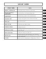
Page 6: ...sembly and reassembly BRAKE SYSTEM STEERING SYSTEM Rear axle Rear wheels Caliper Brake pedal Master cylinder Steering control valve HYDRAULIC SYSTEM MASTS AND FORKS Tank Pump Control valve Lift and ti...

Page 7: ...Vehicle Exterior 1 1 Models 1 1 Serial Number Locations 1 2 Chassis and Mast Model Identification 1 3 Dimensions 1 4 Technical Data 1 5 1 GENERAL INFORMATION...

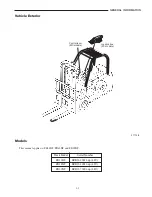
Page 8: ...B16NT EFB11 20011 up 48V FB18NT EFB13 20011 up 48V FB20NT EFB13 70001 up 48V 1 1 GENERAL INFORMATION 211128 Vehicle Exterior Models This manual applies to FB16NT FB18NT and FB20NT Joystick box FC mode...

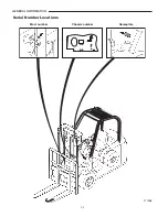
Page 9: ...1 2 GENERAL INFORMATION Mast number Chassis number Nameplate 211268 Serial Number Locations...

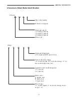
Page 10: ...4400 lb Maximum lifting height 30 stands for 3000 mm 118 in Order of the minor change A for the original B for the first change C for the second change and so on Applicable truck model designation 15...

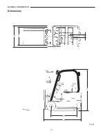
Page 11: ...1 4 GENERAL INFORMATION Dimensions B E F A D C 211269...

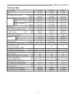
Page 12: ...10 Rear 15 4 5 8 15 4 5 8 140 55 9 Turning Radius mm in 1517 59 7 1620 63 8 1645 64 8 Travel Speeds Unloaded Loaded km h mph 17 17 10 6 10 6 17 17 10 6 10 6 17 17 10 6 10 6 Gradeability Loaded 27 25...

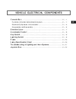
Page 13: ...ponents in Console Box 2 5 Disassembly and Reassembly 2 6 Direction Lever 2 7 Accelerator Control 2 8 Key Switch 2 9 Lighting Switch 2 9 Fuses 2 10 Lamp Specification Chart 2 10 Troubleshooting of Lig...

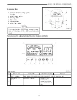
Page 14: ...light fastened when 2 operator sits on seat seat switch is turned on 2 1 VEHICLE ELECTRICAL COMPONENTS Console Box 1 Central vehicle monitoring system CVMS 2 Mode selector button 3 Steering tilt lever...

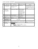
Page 15: ...attery needs to be warning light recharged soon 4 ON indicates battery needs to be recharged and lifting function inoperable 5 Brake fluid level indicator Normal fluid level Low fluid level 6 Parking...

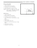
Page 16: ...ock until it is changed When MPH is selected the clock will change to a 12 hour clock Setting the clock 1 Apply the parking brake 2 Place the direction lever in NEUTRAL 3 Turn the key switch to the I...

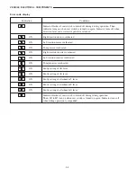
Page 17: ...erheated ON Right traction inverter overheated ON Left traction inverter overheated ON Pump inverter overheated ON Faulty setting of lift lever ON Faulty setting of tilt lever ON Faulty setting of att...

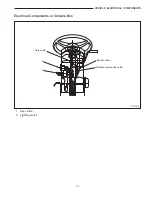
Page 18: ...2 5 VEHICLE ELECTRICAL COMPONENTS Electrical Components in Console Box 2 1 Horn cable Monitor cable Direction lever switch cable 1 Key switch 2 Lighting switch 211132...

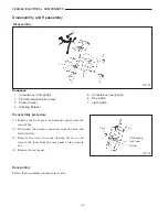
Page 19: ...panel 6 Key switch 7 Light switch Disassembly procedure 1 Remove the front panel and monitor panel from the console box 2 Disconnect the harness connectors from the horn and direction lever 3 Remove t...

Page 20: ...2 7 VEHICLE ELECTRICAL COMPONENTS Direction Lever Structure 1 2 3 4 4 211135 1 Lever 2 Harness 3 Connector 4 Screw...

Page 21: ...BUY NOW Then Instant Download the Complete Manual Thank you very much...

Reviews: