3
Your company internal use only.
Copyright (C) Mitsubishi Electric Corporation.
DY-5MU4R69-T-3,4
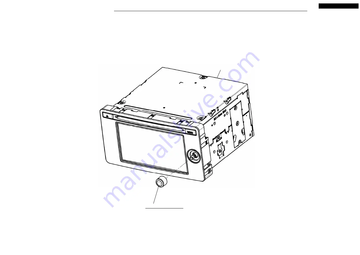
DISASSEMBLING PROCEDURES
M025 : ASSY-KNOB
S2-CHASSIS
●
Disassembling procedures
In reverse of assembling procedures.
●
Assembling procedures
1. Attach M025 to S2-CHASSIS.


