Mitsubishi City multi PCFY-P Installation Manual Download Page 2

Contents

1. Safety precautions ........................................................................................ 2

2. Installation location ....................................................................................... 3

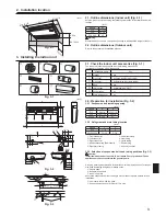
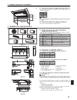
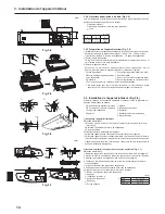
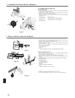
3. Installing the indoor unit................................................................................ 3

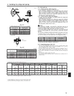
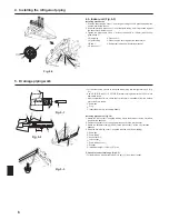
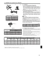
4. Installing the refrigerant piping  .................................................................... 5

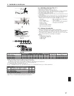
5. Drainage piping work .................................................................................... 6

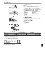
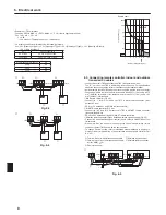
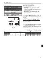
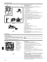
6. Electrical work .............................................................................................. 7

7. Test run ....................................................................................................... 10


Before installing the unit, make sure you read all the “Safety precau-

tions”.


Please report to your supply authority or obtain their consent before 

connecting this equipment to the power supply system. 

 Warning:

Describes precautions that must be observed to prevent danger of injury or 

death to the user.

 Caution:

Describes precautions that must be observed to prevent damage to the unit.

After installation work has been completed, explain the “Safety Precautions,” use, 

and  maintenance  of  the  unit  to  the  customer  according  to  the  information  in  the 

Operation Manual and perform the test run to ensure normal operation. Both the 

Installation Manual and Operation Manual must be given to the user for keeping. 

These manuals must be passed on to subsequent users.

 : Indicates a part which must be grounded.

 Warning:

Carefully read the labels affixed to the main unit.

 Warning:

•  Ask a dealer or an authorized technician to install the unit.

•  For installation work, follow the instructions in the Installation Manual and 

use tools and pipe components specifically made for use with refrigerant 

specified in the outdoor unit installation manual.

•  The unit must be installed according to the instructions in order to mini-

mize the risk of damage from earthquakes, typhoons, or strong winds. An 

incorrectly installed unit may fall down and cause damage or injuries.

•  The unit must be securely installed on a structure that can sustain its weight. 

•  If the air conditioner is installed in a small room, measures must be taken 

to  prevent  the  refrigerant  concentration  in  the  room  from  exceeding  the 

safety limit in the event of refrigerant leakage. Should the refrigerant leak 

and cause the concentration limit to be exceeded, hazards due to lack of 

oxygen in the room may result.

•  Ventilate the room if refrigerant leaks during operation. If refrigerant comes 

into contact with a flame, poisonous gases will be released.

•  All electric work must be performed by a qualified technician according to 

local regulations and the instructions given in this manual. 

•  Use only specified cables for wiring.

•  The terminal block cover panel of the unit must be firmly attached.\

•  Use only accessories authorized by Mitsubishi Electric and ask a dealer or 

an authorized technician to install them.

•  The  user  should  never  attempt  to  repair  the  unit  or  transfer  it  to  another 

location.

•  After installation has been completed, check for refrigerant leaks. If refrig-

erant leaks into the room and comes into contact with the flame of a heater 

or portable cooking range, poisonous gases will be released.

•  When installing or relocating, or servicing the air conditioner, use only the 

specified refrigerant (R410A) to charge the refrigerant lines. Do not mix it 

with any other refrigerant and do not allow air to remain in the lines. 

  If air is mixed with the refrigerant, then it can be the cause of abnormal high 

pressure in the refrigerant line, and may result in an explosion and other 

hazards. 

  The  use  of  any  refrigerant  other  than  that  specified  for  the  system  will 

cause mechanical failure or system malfunction or unit breakdown. In the 

worst  case,  this  could  lead  to  a  serious  impediment  to  securing  product 

safety. 

1.1.  Before installation (Environment)

 Caution:

•  Do not use the unit in an unusual environment. If the air conditioner is in-

stalled in areas exposed to steam, volatile oil (including machine oil), or sulfu

-

ric gas, areas exposed to high salt content such as the seaside, the perform

-

ance can be significantly reduced and the internal parts can be damaged.

•  Do  not  install  the  unit  where  combustible  gases  may  leak,  be  produced, 

flow, or accumulate. If combustible gas accumulates around the unit, fire or 

explosion may result.

•  Do not keep food, plants, caged pets, artwork, or precision instruments in 

the direct airflow of the indoor unit or too close to the unit, as these items 

can be damaged by temperature changes or dripping water.

•  When the  room  humidity  exceeds  80%  or  when  the  drainpipe  is  clogged, 

water may drip from the indoor unit. Do not install the indoor unit where 

such dripping can cause damage.

•  When  installing  the  unit  in  a  hospital  or  communications  office,  be  pre-

pared  for  noise  and  electronic  interference.  Inverters,  home  appliances, 

high-frequency medical equipment, and radio communications equipment 

can  cause  the  air  conditioner  to  malfunction  or  breakdown.  The  air  con-

ditioner  may  also  affect  medical equipment,  disturbing  medical  care,  and 

communications equipment, harming the screen display quality.

1.2.  Before installation or relocation

 Caution:

•  Be  extremely  careful  when  transporting the  units. 2  or  more  persons  are 

needed to handle the unit, as it weighs 44 lbs. (20 kg) or more. Do not grasp 

the packaging bands. Wear protective gloves as you can injure your hands 

on the fins or other parts.

•  Be sure to safely dispose of the packaging materials. Packaging materials, 

such as nails and other metal or wooden parts may cause stabs or other 

injuries.

•  Thermal insulation of the refrigerant pipe is necessary to prevent condensation. 

If the refrigerant pipe is not properly insulated, condensation will be formed.

•  Place thermal insulation on the pipes to prevent condensation. If the drain-

pipe is installed incorrectly, water leakage and damage to the ceiling, floor, 

furniture, or other possessions may result.

•  Do not clean the air conditioner unit with water. Electric shock may result.

•  Tighten  all  flare  nuts  to  specification  using  a  torque  wrench.  If  tightened 

too much, the flare nut can break after an extended period.

1.3.  Before electric work

 Caution:

•  Be sure to install circuit breakers. If not installed, electric shock may result.

•  For the power lines, use standard cables of sufficient capacity. Otherwise, 

a short circuit, overheating, or fire may result.

•  When installing the power lines, do not apply tension to the cables.

•  Be sure to ground the unit. If the unit is not properly grounded, electric 

shock may result.

• 

Use circuit breakers (ground fault interrupter, isolating switch (+B fuse), and 

molded case circuit breaker) with the specified capacity. If the circuit breaker 

capacity is larger than the specified capacity, breakdown or fire may result.

1.4.  Before starting the test run

 Caution:

•  Turn on the main power switch more than 12 hours before starting opera

-

tion. Starting operation just after turning on the power switch can severely 

damage the internal parts.

•  Before starting operation, check that all panels, guards and other protec-

tive  parts  are  correctly  installed.  Rotating,  hot,  or  high  voltage  parts  can 

cause injuries.

•  Do not operate the air conditioner without the air filter set in place. If the air 

filter is not installed, dust may accumulate and breakdown may result.

•  Do not touch any switch with wet hands. Electric shock may result.

•  Do not touch the refrigerant pipes with bare hands during operation.

• 

After stopping operation, be sure to wait at least five minutes before turning 

off the main power switch. Otherwise, water leakage or breakdown may result.

1.  Safety precautions

Note:

The phrase “Wired remote controller” in this installation manual refers to the PAR-21MAA.

If you need any information for the other remote controller, please refer to either the installation manual or initial setting manual which are included in these 

box.

Summary of Contents for City multi PCFY-P

Page 1: ...ioner unit FOR INSTALLER MANUEL D INSTALLATION Avant d installer le climatiseur lire attentivement ce manuel ainsi que le manuel d installation de l appareil exté rieur pour une utilisation sûre et correct POUR L INSTALLATEUR English Français MANUAL DE INSTALACIÓN Para un uso seguro y correcto lea detalladamente este manual de instalación antes de montar la unidad de aire acondicionado PARA EL INS...

Page 2: ... as the seaside the perform ance can be significantly reduced and the internal parts can be damaged Do not install the unit where combustible gases may leak be produced flow or accumulate If combustible gas accumulates around the unit fire or explosion may result Do not keep food plants caged pets artwork or precision instruments in the direct airflow of the indoor unit or too close to the unit as...

Page 3: ...tand the weight of the unit 2 2 Outline dimensions Outdoor unit Refer to the outdoor unit installation manual Fig 3 1 U N IT 3 2 Preparation for installation Fig 3 2 3 2 1 Suspension bolt installing spacing inch Models A B P15 36 1 8 37 13 16 P24 48 11 16 50 3 8 P30 36 61 5 16 63 3 2 2 Refrigerant and drain tubing location inch Models C D P15 7 1 4 8 P24 P30 P36 7 1 16 7 7 8 A Front side outlet F ...

Page 4: ...ling procedures 1 Install the washer 1 supplied with the unit and the nuts to be locally procured 2 Set hook the unit through the suspending bolts 3 Tighten the nuts Check the unit installing condition Check that the unit is horizontal between the right and left sides Check that the front and the rear of suspending brackets are horizontal To keep drainage the unit is inclined to the suspending bra...

Page 5: ... When commercially available copper pipes are used wrap liquid and gas pipes with commercially available insulation materials heat resistant to 212 F 100 C or more thickness of 1 2 in 12 mm or more The indoor parts of the drain pipe should be wrapped with polyethylene foam in sulation materials specific gravity of 0 03 thickness of 23 64 in 9 mm or more Apply thin layer of refrigerant oil to pipe ...

Page 6: ... 7 supplied with the unit Seam taping A Drain pan B Drain tubing C Socket cover 6 D Joint socket 5 E Drain tubing cover 7 F Stopper G Instertion length 1 15 32 in 37 mm 5 Check for correct drainage Fig 5 3 Fill the drain pan with water of about 1 4 gal 1 L from the air outlet Fig 5 2 Fig 5 3 4 3 Indoor unit Fig 4 3 Installing procedures 1 Slide the supplied pipe cover 2 over the gas tubing until i...

Page 7: ...se F0 15A or less 2 2 1 14 2 1 14 2 1 14 15 15 15 15A current sensitivity 3 F0 20A or less 2 3 3 12 3 3 12 3 3 12 20 20 20 20A current sensitivity 3 F0 30A or less 2 5 3 10 5 3 10 5 3 10 30 30 30 30A current sensitivity 3 Apply to IEC61000 3 3 about max permissive system impedance 1 The Ground fault interrupter should support inverter circuit The Ground fault interrupter should combine using of lo...

Page 8: ...ote controller 3 Wireless remote controller When installing wireless signal receiver Fig 6 5 Connect the wire of wireless signal receiver 9 pole cable to CN90 of indoor con troller board When more than two units are run under group control using wireless remote controller connect TB15 each with the same number To change Pair No setting refer to installation manual attached to wireless re mote cont...

Page 9: ...setting branch numbers 1 How to set addresses Example If Address is 3 remain SW12 for over 10 at 0 and match SW11 for 1 to 9 with 3 2 How to set branch numbers SW14 Series R2 only Match the indoor unit s refrigerant pipe with the BC controller s end connection number Remain other than series R2 at 0 The rotary switches are all set to 0 when shipped from the factory These switches can be used to se...

Page 10: ...ollers setting If 2 remote controllers are connected set one to Main and the other to Sub For setting procedures refer to Function selection of remote controller in the op eration manual for the indoor unit Fig 6 9 Fig 6 8 Fig 6 7 Fig 7 1 Do not carry out this test on the control wiring low voltage circuit termi nals Warning Do not use the air conditioner if the insulation resistance is less than ...

Page 11: ......

Page 12: ...rnes de l appareil être endommagées Ne pas installer l appareil dans des endroits où des gaz de combustion peu vent s échapper se dégager ou s accumuler L accumulation de gaz de com bustion autour de l appareil peut provoquer un incendie ou une explosion Ne pas placer d aliments de plantes d animaux en cage d objets d art ou d instruments de précision dans la soufflerie d air direct de l appareil ...

Page 13: ...ures Appareil extérieur Consulter le manuel d installation de l appareil extérieur Fig 3 1 U N IT 3 2 Préparation à l installation Fig 3 2 3 2 1 Espacement et installation du boulon de suspension inch Modèles A B P15 36 1 8 37 13 16 P24 48 11 16 50 3 8 P30 36 61 5 16 63 3 2 2 Emplacement des tuyaux d évacuation et du réfrigérant inch Modèles C D P15 7 1 4 8 P24 P30 36 7 1 16 7 7 8 A Sortie de la f...

Page 14: ...doubles 1 Suspendre l appareil directement Méthodes d installation 1 Mettre en place la rondelle 1 fournie avec l appareil et les écrous sera fourni localement 2 Accrocher l appareil aux boulons de suspension 3 Serrer les écrous Vérifier la condition d installation de l appareil Vérifier que l appareil est à l horizontale entre les côtés droit et gauche Vérifier que l appareil est continuellement ...

Page 15: ...tuyaux de liquide et de gaz avec de la matière isolante vendue dans le commerce sur le marché résistant à une chaleur de 212 F 100 C ou supérieure et d une épaisseur de 1 2 in 12 mm ou plus Les parties intérieures du tuyau d écoulement doivent également être entourées de matière isolante en mousse de polyéthylène avec une poids spécifique de 0 03 et de 23 64 in 9 mm d épaisseur ou plus Appliquer u...

Page 16: ...du tuyau d évacuation Bandage de soudure A Bac d évacuation B Tuyauterie d évacuation C Gaine de la douille 6 D Douille 5 E Gaine de la tuyauterie d évacuation 7 F Arrêt G Longueur d insertion 1 15 32 in 37 mm 5 Vérifier que le système d évacuation est correct Fig 5 3 Remplir le bac d évacuation avec environ 1 4 gal 1 L d eau des sorties d air Fig 5 2 Fig 5 3 4 3 Appareil intérieur Fig 4 3 Méthode...

Page 17: ...aque pôle doit être assuré par l installation de climatisation Fig 6 2 A Disjoncteur de fuite à la terre B Commutateur local Disjoncteur C Appareil intérieur D Boîte de tirage 6 Installations électriques Fig 6 1 C C C C C A B D 230V D C TB2 TB5 TB15 S 1 2 M1 L1 L2 GR M2 A B 230V Fig 6 2 Courant de fonctionnement total de l appareil intérieur Épaisseur minimum câble mm AWG Disjoncteur de câblage NF...

Page 18: ...nal sans fil câble à 9 pôles au connect eur CN90 de la carte de commande intérieure Lorsque plus de deux appareils fonctionnent sous la commande de groupe avec télécommande sans fil raccorder chaque borne TB15 avec le même nombre Pour modifi er la confi guration de No de paire voir le manuel d installation joint à la télécommande sans fil Le No de paire pour la confi guration par défaut de l appar...

Page 19: ...esses Exemple si l adresse est 3 laissez SW12 valeurs à partir de 10 sur 0 et placez SW11 valeurs de 1 à 9 sur 3 2 Comment régler les numéros de branche séries R2 uniquement Associez le tuyau de réfrigérant de l appareil intérieur et le numéro de raccorde ment situé sur l extrémité du boîtier de commandes xC Laissez SW14 autre que R2 sur 0 Les commutateurs rotatifs sont tous réglés sur 0 au départ...

Page 20: ... la télécommande à travers la partie supérieure coupée puis sceller l encoche avec du mastic de la même façon que ci dessus B 1 Pour faire passer le cordon de la télécommande derrière la télécommande B 2 Pour faire passer le cordon de la télécomamnde à travers la partie supérieure 3 Pour l installer directement au mur C Mur D Conduit E Contre écrou F Manchon G Boîte de commutation H Cordon de la t...

Page 21: ...e direction de l air ou sur la grille d admission Vé rifi er le fonctionnement des ailettes ou de la grille 6 Vérifi er le bon fonctionnement du ventilateur de l appareil extérieur 7 Arrêter l essai de fonctionnement en appuyant sur la touche ON OFF Marche Arrêt Arrêt 8 Enregistrez un numéro de téléphone Le numéro de téléphone de l atelier de réparation de l agence commerciale etc à contacter en c...

Page 22: ...stale la unidad donde se puedan verter producir circular o acumular gases inflamables Si se acumula gas inflamable en zonas próximas a la unidad se podría producir un incendio o una explosión No coloque alimentos plantas animales obras de arte o instrumentos de precisión en la salida de aire directa de la unidad exterior o demasiado cer ca de ella ya que los cambios de temperatura o el agua que go...

Page 23: ...de instalación de la unidad exterior Fig 3 1 U N IT 3 2 Preparación para la instalación Fig 3 2 3 2 1 Determinación de las posiciones de instalación de los pernos de suspensión inch Modelos A B P15 36 1 8 37 13 16 P24 48 11 16 50 3 8 P30 36 61 5 16 63 3 2 2 Ubicación de los tubos de refrigerante y drenaje inch Modelos C D P15 7 1 4 8 P24 P30 36 7 1 16 7 7 8 A Salida de aire frontal F Tubería de dr...

Page 24: ...r medio de los pernos de suspensión 3 Apriete las tuercas Comprobación de las condiciones de instalación de la unidad Comprobar que la unidad haya quedado en posición horizontal de izquierda a derecha Compruebe que la parte delantera y trasera de los soportes de suspensión se encuentran completamente horizontales Para mantener un buen drenaje la unidad queda inclinada en los soportes de suspensión...

Page 25: ...C o más espe sor de 1 2 in 12 mm o más Las piezas interiores del tubo de drenaje tienen que estar envueltas en materi ales aislantes de espuma de polietileno gravedad específica de 0 03 y espesor de 23 64 in 9 mm o más Aplique una capa delgada de aceite refrigerante a la superficie tubo y de la junta de asiento antes de apretar la tuerca de abocardado Utilice dos llaves de apriete para apretar las...

Page 26: ...ad Tapando la junta A Depósito de drenaje B Tubo de drenaje C Tapón del adaptador 6 D Adaptador de junta 5 E Tapón del tubo de drenaje 7 F Tapón G Longitud de inserción 1 15 32 in 37mm 5 Comprobación de un drenaje correcto Fig 5 3 Llene el depósito de drenaje con 1 4 gal 1 litro de agua aproximadamente ver tida desde la salida de aire Fig 5 2 Fig 5 3 4 3 Unidad interior Fig 4 3 Procedimientos de i...

Page 27: ...5 15 Sensibilidad de corriente de 15 A 3 F0 20 A o menos 2 3 3 12 3 3 12 3 3 12 20 20 20 Sensibilidad de corriente de 20 A 3 F0 30 A o menos 2 5 3 10 5 3 10 5 3 10 30 30 30 Sensibilidad de corriente de 30 A 3 Aplíquese el IEC61000 3 3 para la impedancia máx admitida en el sistema 1 El interruptor de falta de tierra debería ser compatible con el circuito del inversor El interruptor de falta de tier...

Page 28: ... M2 de la unidad interior TB5 a un mando a distancia M NET 2 cables no polarizados DC 24 a 30 V entre M1 y M2 Mando a distancia M NET 3 Controlador remoto inalámbrico al instalar un receptor de señales inalámbrico Fig 6 5 Conecte el cable del receptor inalámbrico cable de 9 polos al CN90 del cuadro del controlador interior Si hay más de dos unidades controladas en grupo mediante un controlador re ...

Page 29: ... SW1 8 también permite ajustar el flujo de aire cuando el termómetro de la calefacción esté desactivado 6 4 Configuración de las direcciones Fig 6 6 Asegúrese de trabajar con la corriente desconectada Hay disponibles dos tipos de configuraciones para los conmutadores giratorios uno para la configuración de las direcciones 1 a 9 y por encima de 10 y otro para configurar los números de los ramales 1...

Page 30: ...dos piezas Tubo conductor de cobre fino Tuercas y casquillos de seguridad A Perfil del control remoto B Espacios necesarios alrededor del control remoto C Paso de instalación 2 Selle la entrada del cable del control remoto con masilla para evitar que puedan entrar gotas de rocío agua cucarachas o gusanos Fig 6 8 A Para instalarlo en la caja de interruptores B Para instalarlo directamente en la par...

Page 31: ......

Page 32: ...on this manual before handing it to the customer Printed in Thailand RG79D804H01 This product is designed and intended for use in the residential commercial and light industrial environment HEAD OFFICE TOKYO BLDG 2 7 3 MARUNOUCHI CHIYODA KU TOKYO 100 8310 JAPAN ...

Reviews: