The Windows Configurator 2408
f & 2404f PROFIBUS Communications Handbook
5-2 2408
f and 2404f PROFIBUS Communications Handbook
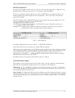
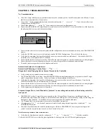
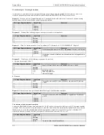
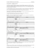
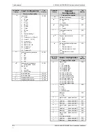
To add a parameter to the PROFIBUS-DP Input Data, simply drag it from the Device Parameter list using the mouse, and drop
it into the Inputs list. Similarly, drop a parameter into the Outputs list to set PROFIBUS-DP Output Data. Alternatively,
double click on a parameter name to add it to the currently selected window - select the list by clicking on it - or use the arrow
button to the left of the input and output lists. You may change the order of the Input and Output List by dragging and
dropping between them. Parameters may be deleted or the list cleared using the buttons on the right hand side of the I/O lists,
or by pressing the right mouse button when the cursor is over a parameter name, whereupon a pop up menu will be displayed.
Select or remove support for ‘Demand Data’ (see Chapter 7) using the check box in the lower part of the screen. Add a short
description of the function of the GSD file in the lower window: this will usually be displayed by your network configuration
tool when selecting a device from the list.
Once the I/O data has been specified to your wishes, save the GSD file to disk: you may use any filename you wish. You may
then import it into your PROFIBUS-DP network configuration tool and use it in an application program. It is possible to save
several different GSD files for the same basic instrument, thereby setting up a library for different applications.
Example:
GSD file to allow gain scheduling using a PID settings stored in a PLC
Input Data
•
Process Variable
Output Data:
•
Proportional Band
•
Integral Time
•
Derivative Time
•
Cutback High
•
Cutback Low
In this application, the PLC monitors ‘Process Variable’ (actual temperature), and when it passes into a particular pre-set band,
sets the output data parameters from settings stored in the PLC.
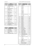
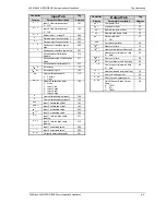
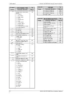
Use the right mouse button when the cursor is over a parameter in the left hand window to determine its tag for demand data
operations.
A limit of 117 total input and output words, including the requirements for demand data, is imposed by the configurator.
When this limit is reached, it will no longer be possible to add parameters into either the input or output lists until other
parameters have been deleted. In any case it is advisable not to exceed 32 input and 32 output words in total, since some
masters are unable to deal with more.
To obtain a summary of the I/O memory map for the current GSD file, select ‘View I/O map’ from the file menu. This may be
pasted into the clipboard and placed into a document if required for project documentation. It may also be printed directly
from the File menu.

