


-
38
-
'13 • PAC-DB-194
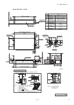
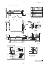
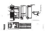
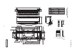
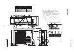
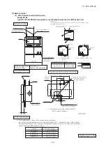
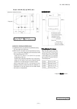
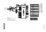
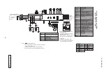
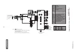
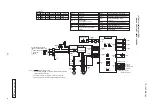
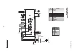
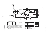
(b) Ceiling suspended type (FDEN)
Models FDEN71VF1, 100VF1
[ ]
Capacitor for FMI
CFI1,2
FMI1,2
Transformer
TrI
SW2
Connector
CNB
~
Z
TB1
Relay for FMI
X1
~
3,6
SW5
Operation check, Drain motor test run
SW7-1
Fuse
F
ThI-R1,2,3
ThI-A
Thc
LED
・
3
LED
・
2
Relay for DM
X4
TB2
Fan motor
(
with thermistor
)
Indication lamp
(
Green-Normal operation
)
Indication lamp
(
Red-Inspection
)
Remote control communication address
Plural units Master
/
Slave setting
Terminal block
(
Power source
)(□
mark
)
Terminal block
(
Signal line
)(□
mark
)
Thermistor
(
Remote control
)
Thermistor
(
Return air
)
Thermistor
(
Heat exchanger
)
LM
Louver motor
SW6
Model capacity setting
RD
CNW0
BL
WH
RD
X1
3
UH
BR
WH
CNM3
C
WH
1
F
(
3.15A
)
1
3
X6
M
H
BK
BL
5
7
L
RD
9
X3
X2
5
BK
BK
CNB WH
1
3
1
3
TB1
220
ー
240V
LED
・
2
SW2
SW6
SW5
SW7
LED
・
3
F
(
3.15A
)
YE
/
GN
TB2
X Y
WH
BK
Tr
I
RD RD BR BR
BK
CNW2
19V
24V
1 2 3 4 5
CNJ WH
BL
BR OR RD
M
LM
WH
CNF2
WH
CNF1
CNR
3
1
WH
X4
CNI
BL
WH
CNW1
M
1
~
M
1
~
XR1
XR2
XR3
XR4
1
2
3
4
5
6
+12
CNT
BL
5
5
5
5
LED4
SW1
LED2 LED3
AMP
SW4
CNB2
WH
CNB
1
2
3
4
CNN
5
6
1
2
BK
CNH
ThI-R1
ThI-A
ThI-R2
t
°
t
°
ThI-R3
t
°
t
°
BK
BK
BK
BK
WH
RD
Receiver PCB
Remote
control
BK
BK
BK
BK
XR5
(
Remote operation input :
volt-free contact
)
(
Operation
)
(
Heating
)
(
Compressor ON
)
(
Inspection
)
Prepare on site
Closed-end connector
■
mark
Control PCB
Color
Mark
BK
Color Marks
Black
BL
Blue
BR
Brown
Color
Mark
RD
Red
WH
White
YE
/
GN Yellow
/
Green
Receiver PCB
7-segment display
Switches for setting
SW1
LED2
Back-up switch
(
Operation
/
Stop
)
SW4
Indication lamp
(
Green-Normal operation
)
LED3
Indication lamp
(
Yellow-Timer
/
Inspection
)
LED4
PK
Pink
OR
Orange
Remote
control
Thc
TB2
Wired specification
Wireless specification
X
Y
X
Y
t
°
Earth
Power source line
Signal line
1 2
3
indoor unit and outdoor unit
Connecting line between
2
C
WH
YE
Yellow
CFI1
FMI1
CNFI1
WH
CFI2
FMI2
CNFI2
WH
PK
YE
Notes 1.
indicates wiring on site.
2. See the wiring diagram of outside unit about the line between
indoor unit and outdoor unit.
3. Use twin core cord
(
0.3mm
2
X2
)
at remote control line.
4. Do not put remote control line alongside power source line.
YE
/
GN
YE
/
GN
OR
OR
OR
OR
※
When wired remote control are used
only
(
wireless type
)
It is necessary to remove the line that is
connected to the receiver.
Remove signal line connected to the receiver
from primary side of terminal block(X,Y
)
.
ATTENTION
①
Insulate with tape the removed line.
②
The LED of that removed connector will
not be able to make any indication.
D
P
F
A
0
0
3
Z
8
2
0