Mitsubishi Heavy Industries SRK10CRS-S Technical Manual & Parts Lists Download Page 38

-


-

 '15 • SRK-T-172

– 29 –

Safety precautions

 CAUTION

Carry out the electrical work for ground lead with care.

v

Do not connect the ground lead to the gas line, water line, lightning conductor or telephone line’s ground lead. Incorrect grounding can cause 

unit faults such as electric shocks due to short-circuiting.

Use the circuit breaker of correct capacity. Circuit breaker 

v

should be able to disconnect all poles under over current.

Using the incorrect one could cause the system failure and fire.
Install isolator or disconnect switch on the power supply wiring 

v

in accordance with the local codes and regulations.

The isolator should be locked in OFF state in accordance with 

EN60204-1.
Be sure to install indoor unit properly according to instruction 

v

manual so that drainage can run off smoothly.

Improper installation of indoor unit can cause dropping water into the 

room and damaging personal property.
Install the drainage pipe to run off drainage securely according

v

to the installation manual.

Incorrect installation of the drainage pipe can cause dropping water

into the room and damaging personal property.
Be sure to install the drainage pipe with descending slope of 

v

1/100 or more, and not to make traps and air-bleedings.

Check if the drainage runs off securely during commissioning and 

ensure the space for inspection and maintenance.
After maintenance, all wiring, wiring ties and the like, should 

v

be returned to their original state and wiring route, and the 

necessary clearance from all metal parts should be secured.
Secure a space for installation, inspection and maintenance 

v

specified in the manual.

Insufficient space can result in accident such as personal injury due 

to falling from the installation place.

Take care when carrying the unit by hand.

v

If the unit weights more than 20kg, it must be carried by two or more 

persons. Do not carry by the plastic straps, always use the carry

handle when carrying the unit by hand. Use gloves to minimize the 

risk of cuts by the aluminum fins.
Dispose of any packing materials correctly.

v

Any remaining packing materials can cause personal injury as it contains

nails and wood. And to avoid danger of suffocation, be sure to keep the

plastic wrapper away from children and to dispose after tear it up.
For installation work, be careful not to get injured with the heat 

v

exchanger, piping flare portion or screws etc.
Be sure to insulate the refrigerant pipes so as not to condense 

v

the ambient air moisture on them.

Insufficient insulation can cause condensation, which can lead to

moisture damage on the ceiling, floor, furniture and any other valuables.
When perform the air-conditioner operation (cooling or drying

v

operation) in which ventilator is installed in the room. In this 

case, using the air-conditioner in parallel with the ventilator,

there is the possibility that drain water may backflow in 

accordance with the room lapse into the negative pressure 

status. Therefore, set up the opening port such as incorporate 

the air into the room that may appropriate to ventilation (For 

example; Open the door a little). In addition, just as above, so 

set up the opening port if the room lapse into negative pressure 

status due to register of the wind for the high rise apartment etc.
Be sure to perform air tightness test by pressurizing with 

v

nitrogen gas after completed refrigerant piping work.

If the density of refrigerant exceeds the limit in the event of refrigerant

leakage in the small room, lack of oxygen can occur,  which can 

cause serious accidents.

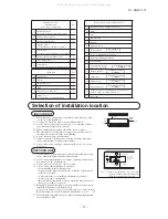
Do not install the unit in the locations listed below.

v

Locations where carbon fiber, metal powder or any powder is floating.

v

Locations where any substances that can affect the unit such as 

v

sulphide gas, chloride gas, acid and alkaline can occur.

Vehicles and ships.

v

Locations where cosmetic or special sprays are often used.

v

Locations with direct exposure of oil mist and steam such as 

v

kitchen and machine plant.

Locations where any machines which generate high frequency 

v

harmonics are used.

Locations with salty atmospheres such as coastlines.

v

Locations with heavy snow (If installed, be sure to provide base 

v

flame and snow hood mentioned in the manual).

Locations where the unit is exposed to chimney smoke.

v

Locations at high altitude (more than 1000m high).

v

Locations with ammonic atmospheres.

v

Locations where heat radiation from other heat source can affect

v

the unit.

Locations without good air circulation.

v

Locations with any obstacles which can prevent inlet and outlet air 

v

of the unit.

Locations where short circuit of air can occur (in case of multiple

v

units installation).

Locations where strong air blows against the air outlet of outdoor unit.

v

Locations where something located above the unit could fall.

v

It can cause remarkable decrease in performance, corrosion and 

damage of components, malfunction and fire.
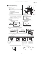
Do not install the indoor unit in the locations listed below (Be

v

sure to install the indoor unit according to the installation manual

for each model because each indoor unit has each limitation).

Locations with any obstacles which can prevent inlet and outlet air 

v

of the unit.

Locations where vibration can be amplified due to insufficient

v

strength of structure.

Locations where the infrared receiver is exposed to the direct sunlight

v

or the strong light beam (in case of the infrared specification unit).

Locations where an equipment affected by high harmonics is placed

v

(TV set or radio receiver is placed within 1m).

Locations where drainage cannot run off safely.

v

It can affect performance or function and etc.
Do not install the outdoor unit in the locations listed below.

v

Locations where discharged hot air or operating sound of the 

v

outdoor unit can bother neighborhood.

Locations where outlet air of the outdoor unit blows directly to 

v

plants. The outlet air can affect adversely to the plant etc.

Locations where vibration can be amplified and transmitted due to 

v

insufficient strength of structure.

Locations where vibration and operation sound generated by the outdoor

v

unit can affect seriously (on the wall or at the place near bed room).

Locations where an equipment affected by high harmonics is placed

v

(TV set or radio receiver is placed within 1m).

Locations where drainage cannot run off safely.

v

It can affect surrounding environment and cause a claim.
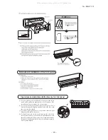
Do not install the unit where corrosive gas (such as sulfurous

v

acid gas etc.) or combustible gas (such as thinner and 

petroleum gases) can accumulate or collect, or where volatile

combustible substances are handled.

Corrosive gas can cause corrosion of heat exchanger, breakage of 

plastic parts and etc. And combustible gas can cause fire.

Do not install the unit near the location where leakage of 

v

combustible gases can occur.

If leaked gases accumulate around the unit, it can cause fire.
Do not use the indoor unit at the place where water splashes 

v

may occur such as in laundries.

Since the indoor unit is not waterproof, it can cause electric shocks

and fire.
Do not install nor use the system close to the equipment that 

v

generates electromagnetic fields or high frequency harmonics.

Equipment such as inverters, standby generators, medical high 

frequency equipments and telecommunication equipments can 

affect the system, and cause malfunctions and breakdowns. The

system can also affect medical equipment and telecommunication

equipment, and obstruct its function or cause jamming.
Do not place any variables which will be damaged by getting wet

v

under the indoor unit.

When the relative humidity is higher than 80% or drainage pipe is 

clogged, condensation or drainage water can drop and it can cause 

the damage of valuables.
Do not install the remote control at the direct sunlight.

v

It can cause malfunction or deformation of the remote control.
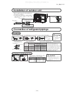
Do not use the unit for special purposes such as storing foods,

v

cooling precision instruments and preservation of animals,

plants or art.

It can cause the damage of the items.
Do not install the outdoor unit in a location where insects and 

v

small animals can inhabit.

Insects and small animals can enter the electric parts and cause 

damage or fire. Instruct the user to keep the surroundings clean.
Do not use the base flame for outdoor unit which is corroded or 

v

damaged due to long periods of operation.

Using an old and damage base flame can cause the unit falling down

and cause personal injury.
Do not use any materials other than a fuse with the correct 

v

rating in the location where fuses are to be used.

Connecting the circuit with copper wire or other metal thread can 

cause unit failure and fire.
Do not touch any buttons with wet hands.

v

It can cause electric shocks.
Do not touch any refrigerant pipes with your hands when the 

v

system is in operation.

During operation the refrigerant pipes become extremely hot or 

extremely cold depending the operating condition, and it can cause 

burn injury or frost injury.
Do not touch the suction or aluminum fin on the outdoor unit.

v

This may cause injury.
Do not put anything on the outdoor unit and operating unit.

v

This may cause damage the objects or injury due to falling to the 

object.

RMA012A086_EN.indb   29

17/11/2014   15:17:38

Do not clean up the unit with water.

v

All manuals and user guides at all-guides.com

Summary of Contents for SRK10CRS-S

Page 1: ... MOUNTED TYPE RESIDENTIAL AIR CONDITIONERS Split system air cooled cooling only type SRK10CRV S S1 SRK13CRV S S1 SRK10CRS S S1 S2 S3 S4 S5 S6 SRK13CRS S S1 S2 S3 S4 S5 S6 Manual No 15 SRK T 172 All manuals and user guides at all guides com a l l g u i d e s c o m ...

Page 2: ...All manuals and user guides at all guides com ...

Page 3: ... 15 SRK T 172 TECHNICAL MANUAL All manuals and user guides at all guides com ...

Page 4: ...control 48 47 4 Custom cord switching procedure 47 3 Auto restart function 2 Unit ON OFF button 47 1 Operation control function by remote control 45 8 Installation location setting 50 10 Outline of automatic operation 51 UTLINE OF COOLING OPERATION 51 11 Protective control function 52 53 54 4ROUBLESHOOTING PROCEDURE F THE AIR CONDITIONER RUNS 4ROUBLESHOOTING PROCEDURE F THE AIR CONDITIONER DOES NO...

Page 5: ...ERVED AFTER SHORTCIRCUIT WIRE BREAKAGE ON SENSOR 56 HECKING THE INDOOR ELECTRICAL EQUIPMENT 56 How to read the model name Example SRK 10 C Series code Cooling only type Product capacity Model name SRK Wall mounted type SRC Outdoor unit RV S All manuals and user guides at all guides com ...

Page 6: ...ion display RUN Green TIMER Yellow HI POWER Green ECONO Orange Safety devices Compressor overheat protection Frost protection Serial signal error protection Fan motor error protection Installation data Refrigerant piping size O D mm Liquid line φ6 35 1 4 Gas line φ9 52 3 8 Connecting method Flare connecting Attached length of piping m Liquid line 0 57 Gas line 0 55 Insulation for piping Necessary ...

Page 7: ...tion display RUN Green TIMER Yellow HI POWER Green ECONO Orange Safety devices Compressor overheat protection Frost protection Serial signal error protection Fan motor error protection Installation data Refrigerant piping size O D mm Liquid line φ6 35 1 4 Gas line φ9 52 3 8 Connecting method Flare connecting Attached length of piping m Liquid line 0 57 Gas line 0 55 Insulation for piping Necessary...

Page 8: ...rmostat Operation display RUN Green TIMER Yellow HI POWER Green ECONO Orange Safety devices Compressor overheat protection Frost protection Serial signal error protection Fan motor error protection Installation data Refrigerant piping size O D mm Liquid line φ6 35 1 4 Gas line φ12 7 1 2 Connecting method Flare connecting Attached length of piping m Liquid line 0 57 Gas line 0 55 Insulation for pip...

Page 9: ...tat Operation display RUN Green TIMER Yellow HI POWER Green ECONO Orange Safety devices Compressor overheat protection Frost protection Serial signal error protection Fan motor error protection Installation data Refrigerant piping size O D mm Liquid line φ6 35 1 4 Gas line φ12 7 1 2 Connecting method Flare connecting Attached length of piping m Liquid line 0 57 Gas line 0 55 Insulation for piping ...

Page 10: ...tion display RUN Green TIMER Yellow HI POWER Green 3D AUTO Green Safety devices Compressor overheat protection Frost protection Serial signal error protection Fan motor error protection Installation data Refrigerant piping size O D mm Liquid line φ6 35 1 4 Gas line φ9 52 5 8 Connecting method Flare connecting Attached length of piping m Liquid line 0 57 Gas line 0 55 Insulation for piping Necessar...

Page 11: ...lay RUN Green TIMER Yellow HI POWER Green 3D AUTO Green Safety devices Compressor overheat protection Frost protection Serial signal error protection Fan motor error protection Installation data Refrigerant piping size O D mm Liquid line φ6 35 1 4 Gas line φ9 52 5 8 Connecting method Flare connecting Attached length of piping m Liquid line 0 57 Gas line 0 55 Insulation for piping Necessary Both si...

Page 12: ...Operation display RUN Green TIMER Yellow HI POWER Green 3D AUTO Green Safety devices Compressor overheat protection Frost protection Serial signal error protection Fan motor error protection Installation data Refrigerant piping size O D mm Liquid line φ6 35 1 4 Gas line φ9 52 5 8 Connecting method Flare connecting Attached length of piping m Liquid line 0 57 Gas line 0 55 Insulation for piping Nec...

Page 13: ...tat Operation display RUN Green TIMER Yellow HI POWER Green 3D AUTO Green Safety devices Compressor overheat protection Frost protection Serial signal error protection Fan motor error protection Installation data Refrigerant piping size O D mm Liquid line φ6 35 1 4 Gas line φ9 52 5 8 Connecting method Flare connecting Attached length of piping m Liquid line 0 57 Gas line 0 55 Insulation for piping...

Page 14: ...stat Operation display RUN Green TIMER Yellow HI POWER Green 3D AUTO Green Safety devices Compressor overheat protection Frost protection Serial signal error protection Fan motor error protection Installation data Refrigerant piping size O D mm Liquid line φ6 35 1 4 Gas line φ9 52 5 8 Connecting method Flare connecting Attached length of piping m Liquid line 0 57 Gas line 0 55 Insulation for pipin...

Page 15: ...thermostat Operation display RUN Green TIMER Yellow HI POWER Green 3D AUTO Green Safety devices Compressor overheat protection Frost protection Serial signal error protection Fan motor error protection Installation data Refrigerant piping size O D mm Liquid line φ6 35 1 4 Gas line φ9 52 5 8 Connecting method Flare connecting Attached length of piping m Liquid line 0 57 Gas line 0 55 Insulation for...

Page 16: ...on display RUN Green TIMER Yellow HI POWER Green 3D AUTO Green Safety devices Compressor overheat protection Frost protection Serial signal error protection Fan motor error protection Installation data Refrigerant piping size O D mm Liquid line φ6 35 1 4 Gas line φ9 52 5 8 Connecting method Flare connecting Attached length of piping m Liquid line 0 57 Gas line 0 55 Insulation for piping Necessary ...

Page 17: ...t Operation display RUN Green TIMER Yellow HI POWER Green 3D AUTO Green Safety devices Compressor overheat protection Frost protection Serial signal error protection Fan motor error protection Installation data Refrigerant piping size O D mm Liquid line φ6 35 1 4 Gas line φ12 7 1 2 Connecting method Flare connecting Attached length of piping m Liquid line 0 57 Gas line 0 55 Insulation for piping N...

Page 18: ...tat Operation display RUN Green TIMER Yellow HI POWER Green 3D AUTO Green Safety devices Compressor overheat protection Frost protection Serial signal error protection Fan motor error protection Installation data Refrigerant piping size O D mm Liquid line φ6 35 1 4 Gas line φ12 7 1 2 Connecting method Flare connecting Attached length of piping m Liquid line 0 57 Gas line 0 55 Insulation for piping...

Page 19: ...tat Operation display RUN Green TIMER Yellow HI POWER Green 3D AUTO Green Safety devices Compressor overheat protection Frost protection Serial signal error protection Fan motor error protection Installation data Refrigerant piping size O D mm Liquid line φ6 35 1 4 Gas line φ12 7 1 2 Connecting method Flare connecting Attached length of piping m Liquid line 0 57 Gas line 0 55 Insulation for piping...

Page 20: ...hermostat Operation display RUN Green TIMER Yellow HI POWER Green 3D AUTO Green Safety devices Compressor overheat protection Frost protection Serial signal error protection Fan motor error protection Installation data Refrigerant piping size O D mm Liquid line φ6 35 1 4 Gas line φ12 7 1 2 Connecting method Flare connecting Attached length of piping m Liquid line 0 57 Gas line 0 55 Insulation for ...

Page 21: ...eration display RUN Green TIMER Yellow HI POWER Green 3D AUTO Green Safety devices Compressor overheat protection Frost protection Serial signal error protection Fan motor error protection Installation data Refrigerant piping size O D mm Liquid line φ6 35 1 4 Gas line φ12 7 1 2 Connecting method Flare connecting Attached length of piping m Liquid line 0 57 Gas line 0 55 Insulation for piping Neces...

Page 22: ...tat Operation display RUN Green TIMER Yellow HI POWER Green 3D AUTO Green Safety devices Compressor overheat protection Frost protection Serial signal error protection Fan motor error protection Installation data Refrigerant piping size O D mm Liquid line φ6 35 1 4 Gas line φ12 7 1 2 Connecting method Flare connecting Attached length of piping m Liquid line 0 57 Gas line 0 55 Insulation for piping...

Page 23: ...hermostat Operation display RUN Green TIMER Yellow HI POWER Green 3D AUTO Green Safety devices Compressor overheat protection Frost protection Serial signal error protection Fan motor error protection Installation data Refrigerant piping size O D mm Liquid line φ6 35 1 4 Gas line φ12 7 1 2 Connecting method Flare connecting Attached length of piping m Liquid line 0 57 Gas line 0 55 Insulation for ...

Page 24: ...8 3 Service space 65 Service space 15 50 Service space 100 Service space 53 5 380 6 448 6 520 Space for installation and service when viewing from the front D A B E C 53 5 Installation plate Unit Hole on wall for right rear piping Hole on wall for left rear piping Gas piping Outlet for wiring Drain hose Liquid piping F E C D B Symbol A φ65 VP16 φ6 35 1 4 Flare Content φ65 φ9 52 3 8 Flare Outlet fo...

Page 25: ...1 6 50 6 12 Terminal block 97 7 42 5 4 0 4 0 138 4 33 5 15 8 290 A C B D E 540 2 16x12 Unit mm Models SRC13CRV S S1 SRC13CRS S S1 S2 S3 S4 S5 S6 φ12 7 1 2 Flare Content C Pipe cable draw out hole E Anchor bolt hole Drain discharge hole Symbol B A Service valve connection gas side M10 4places φ20 2places Service valve connection liquid side φ6 35 1 4 Flare 63 4 390 6 390 6 69 4 111 6 510 158 4 780 ...

Page 26: ... mm 60 17 3 150 Unit mm 60 17 3 150 Models SRK10CRS S S1 S2 S3 S4 S5 S6 SRK13CRS S S1 S2 S3 S4 S5 S6 Models SRK10CRV S S1 SRK13CRV S S1 Unit mm 60 17 3 150 Unit mm 60 17 3 150 All manuals and user guides at all guides com a l l g u i d e s c o m ...

Page 27: ...otor Flap motor Varistor Th2 T Room temp thermistor Heat exchanger thermistor Terminal block F Th1 Power source 220 230 240V 50Hz YG LB BR Printed circuit board T YG BL BR WH BK TO OUTDOOR UNIT Th1 Th2 Wireless R Amp Display CNE CNG YE WH RD M CNW IC15 ZNR 1 5 3 CNU CF I 52C 4 52C 3 52C F 250V 3 15A CONTROL BOX 1 2 Back up Sw CNM N t 1 FM I t 1 Indoor units Models SRK10CRV S S1 SRK13CRV S S1 All m...

Page 28: ... FM ZNR FM I Fuse Fan motor Flap motor Varistor Louver motor RIGHT LM Th2 T Room temp thermistor Heat exchanger thermistor Terminal block F Th1 Power source 220 230 240V 50Hz YG LB BR Printed circuit board T YG BL BR WH BK TO OUTDOOR UNIT Th1 Th2 Wireless R Amp Display CNE CNG YE WH RD M CNW CNY IC15 ZNR 1 5 3 CNU CF I 52C 4 52C 3 52C F 250V 3 15A CONTROL BOX 1 2 Back up Sw CNX CNM N R Louver moto...

Page 29: ...M TERMINAL BLOCK INDOOR UNIT T1 TERMINAL BLOCK OUTDOOR UNIT T2 MOTOR PROTECTOR 51C R C CM S 51C 3 1 2 BLACK BLACK RED BLACK WHITE 2 N 1 T1 Power source 220 240V 50Hz RUNNING CAPACITOR FOR COMPRESSOR RUNNING CAPACITOR FOR FAN MOTOR CFo Cc FAN MOTOR COMPRESSOR MOTOR FMo CM DESCRIPTION ITEM TERMINAL BLOCK INDOOR UNIT T1 TERMINAL BLOCK OUTDOOR UNIT T2 2 N 1 T1 Power source 220 240V 50Hz R C S WHITE CM...

Page 30: ... 2 10 5 P a Mid Octave Band Frequency Hz 63 125 250 500 1000 2000 4000 8000 10 20 30 40 50 60 70 N70 N60 N50 N40 N30 N20 Mike position at highest noise level in position as mentined below Distance from front side 1m Mike position as below 0 8m 1m Unit Mike position Center Low points 10 20 30 40 50 60 70 Sound Pressure Level dB Standard 2 10 5 P a Mid Octave Band Frequency Hz 63 125 250 500 1000 20...

Page 31: ... 125 250 500 1000 2000 4000 8000 10 20 30 40 50 60 70 N70 N60 N50 N40 N30 N20 10 20 30 40 50 60 70 Sound Pressure Level dB Standard 2 10 5 P a Mid Octave Band Frequency Hz 63 125 250 500 1000 2000 4000 8000 10 20 30 40 50 60 70 N70 N60 N50 N40 N30 N20 Mike position at highest noise level in position as mentined below Distance from front side 1m Mike position as below 0 8m 1m Unit Mike position Cen...

Page 32: ... Flare connecting Heat exchanger sensor Liquid pipe ø6 35 Check joint Service valve Liquid Flare connecting Heat exchanger Compressor Capillary tube Accumulator Service valve Cooling cycle Gas Capillary tube 10 ø9 52 Gas pipe 13 ø12 7 All models All manuals and user guides at all guides com ...

Page 33: ...0m Outdoor unit is higher Max 10m Outdoor unit is lower Min 3 minutes Max 10 times h Min 85 of rating Vertical height difference between outdoor unit and indoor unit Power source voltage Voltage at starting Frequency of ON OFF cycle ON and OFF interval Rating 10 14 16 18 20 22 15 20 25 30 35 40 0 6 0 7 0 8 0 9 1 0 1 1 1 2 1 3 43 24 ISO T1 Standard Condition Indoor air W B temperature C W B Cooling...

Page 34: ...of cooling capacity in relation to one way length of refrigerant piping How to obtain the cooling capacity Piping length m Cooling 7 1 0 10 0 99 0 975 15 3600 SRK13CRV S SRK13CRV S 3510 All manuals and user guides at all guides com ...

Page 35: ... 39 2 09 2 09 2 24 2 19 2 47 2 28 2 57 2 26 2 64 2 21 2 81 2 22 2 94 2 10 Hi indoor temperature Outdoor DB TC SHC TC SHC TC SHC TC SHC TC SHC TC SHC TC SHC 10 3 04 2 52 3 18 2 48 3 30 2 59 3 36 2 56 3 42 2 53 3 52 2 62 3 61 2 55 12 2 99 2 50 3 13 2 46 3 25 2 57 3 31 2 54 3 37 2 51 3 48 2 61 3 58 2 52 14 2 93 2 47 3 08 2 43 3 21 2 55 3 27 2 52 3 33 2 49 3 44 2 59 3 54 2 51 16 2 87 2 44 3 02 2 41 3 ...

Page 36: ...oor temperature Outdoor DB TC SHC TC SHC TC SHC TC SHC TC SHC TC SHC TC SHC 10 4 06 3 26 4 25 3 18 4 40 3 20 4 48 3 14 4 55 3 07 4 69 3 03 4 81 2 85 12 3 98 3 22 4 17 3 14 4 34 3 17 4 42 3 11 4 50 3 04 4 64 3 00 4 77 2 83 14 3 91 3 17 4 10 3 10 4 28 3 13 4 36 3 08 4 44 3 01 4 58 2 98 4 72 2 81 16 3 83 3 13 4 02 3 06 4 21 3 10 4 29 3 04 4 38 2 98 4 53 2 95 4 67 2 79 18 3 75 3 09 3 95 3 02 4 14 3 06...

Page 37: ...njury due to anomalously high pressure in the refrigerant The electrical installation must be carried out by the qualified v electrician in accordance with the norm for electrical work and national wiring regulation and the system must be connected to the dedicated circuit Power supply with insufficient capacity and incorrect function done by improper work can cause electric shocks and fire Be sur...

Page 38: ...Locations where short circuit of air can occur in case of multiple v units installation Locations where strong air blows against the air outlet of outdoor unit v Locations where something located above the unit could fall v It can cause remarkable decrease in performance corrosion and damage of components malfunction and fire Do not install the indoor unit in the locations listed below Be v sure t...

Page 39: ...exposed to the direct rays of the sun or the strong rays of the street lighting A place where it can be easily drained A place separated at least 1m away from the television or the radio To prevent interfence to images and sounds A place that home appliance and household goods etc aren t below unit INDOOR UNIT 10 cm 5 cm 10 cm Left side CM Air intake CM 10 cm Air outlet Air intake No obstacles Ser...

Page 40: ...y piping length and vertical height difference One way piping length 15 m Vertical height difference h Outdoor unit is lower 10 m Outdoor unit is higher 10 m Drilling of holes and fixture sleeve Option parts RMA012A086_087_Install_EN indd 31 21 Nov 14 12 04 27 All manuals and user guides at all guides com ...

Page 41: ... 17 38 Connecting power source by power cable connecting diagram Terminal and power cable on the indoor unit Brown Power source Blue Yellow Green L N 1 2 Terminal on the outdoor unit 1 2 All manuals and user guides at all guides com a l l g u i d e s c o m ...

Page 42: ... slightly until the latch works then push the center portion slightly 3 To remove pull up the panel to the position shown in right illustration and pull it toward you 4 To install insert the air inlet panel arm into the slot on the front panel from the position shown in right illustration hold the panel at both ends of lower part lower it downward slowly then push it slightly until the latch works...

Page 43: ... flaring block will vary depending on the type of a flare tool in use If a conventional flare tool is used please use a copper pipe gauge or a similar instrument to check protrusion so that you can keep measurement B to a correct value Clutch type flare tool for R410A Conventional R22 flare tool Clutch type Wing nut type F 6 35 0 0 0 5 1 0 1 5 1 5 2 0 F 9 52 0 0 0 5 1 0 1 5 1 5 2 0 F 12 7 0 0 0 5 ...

Page 44: ...ation valve two way valve Gauge manifold Designed specifically for R410A Tighten all flare nuts in the pipings both indoor and outside wall so as not to cause leak Connectoperationvalve chargehose manifold valve and vacuum pump as is illustrated right Open manifold valve handle Lo to its full width and perform vacuum or evacuation Continue the vacuum or evacuation operation for 15 minutes or more ...

Page 45: ...e compressor Explain to the customer on the correct usage of the air conditioner in simple layman s terms Make sure that drain flows properly Battery Cover Fixing to pillar or wall v Conventionally operate the wireless remote control by holding in your hand v Avoid installing it on a clay wall etc Screws CAUTION Do not use new and old batteries together How to relocate or dispose of the unit v In ...

Page 46: ... the joints of the operation valve Operation valve is fully open The pipe joints for indoor and outdoor pipes have been insulated Test run Air conditioning operation is normal No abnormal noise Water drains smoothly Protective functions are not working The remote control is normal Operation of the unit has been explained to the customer Three minute restart preventive timer When the air conditione...

Page 47: ...m temperature This button changes the present time and TIMER time ON TIMER button This button selects ON TIMER operation SLEEP button This button changes to SLEEP operation CLEAN switch This swich changes the CLEAN mode OPERATION MODE select button Each time the button pushed the indicator is switched over in turn ON OFF luminous button Press for starting operation press agian for stopping AIR FLO...

Page 48: ... This button changes the air flow left right mode SLEEP button This button changes to SLEEP operation CLEAN switch This switch changes the CLEAN mode ON TIMER button This button selects ON TIMER operation AIR FLOW LEFT RIGHT button 3D AUTO button This button sets 3D AUTO operation This button cancels the ON timer OFF timer and SLEEP operation CANCEL button ACL switch Switch for resetting microcomp...

Page 49: ...ied receiving and operation can not be done a Modifying the indoor unit s printed circuit board Take out the printed circuit board from the control box and cut off jumper wire J6 using wire cutters After cutting of the jumper wire take measures to prevent contact with the other the lead wires etc b Modifying the wireless remote control i Remove the battery ii Cut the jumper wire shown in the figur...

Page 50: ...0 Angle of Flap from Horizontal Center installation Remote control display Right end installation Left end installation Angle of Louver Left Approx 45 Left Approx 45 Left Approx 20 Left Approx 30 Center Left Approx 20 Right Approx 20 Center Right Approx 45 Right Approx 20 Left Approx 20 Center Right Approx 20 Right Approx 30 Right Approx 45 Louver stopped Swing Spot Wide In COOL DRY FAN operation ...

Page 51: ...uver Right louver Left louver Right louver 1 4 6 3D auto operation only SRK10CJV 2 13CJV 2 Control the flap and louver by 3D AUTO button on the wireless remote control Fan speed and air flow direction are automatically controlled allowing the entire room to efficiently conditioned a Detail of operation i Perform STEP1 STEP2 STEP3 STEP4 one time ii After performing STEP4 in i above the next steps t...

Page 52: ...FF button to stop ii Press the AIR FLOW UP DOWN button and the AIR FLOW LEFT RIGHT button together for 5 seconds or more iii Setting the air conditioning installation location iv Press the ON OFF button Airflow range Airflow range Airflow range Left End Installation Center Installation Right End Installation Center Installation Right End Installation Left End Installation i iv ii iii All manuals a...

Page 53: ...perature C b The unit checks the temperature every 30 minutes after the start of operation and if the result of check is not same as the previous operation mode changes the operation mode c When the unit is started again within one hour after the stop of automatic operation or when the automatic operation is se lected during cooling or dehumidifying operation the unit is operated in the previous o...

Page 54: ... thermal operation is not effective for 3 minutes so operation continues as is in the operation mode After 3 minutes has passed the thermal operation is effective However stopping the compressor via a stop signal or protection control has priority d Abnormality of outdoor unit When the indoor heat exchanger temperature does not fall to 25 C or below for 40 minutes after 5 minutes have elap sed sin...

Page 55: ...shooting procedure If the air conditioner does not run at all If the air conditioner does not run at all diagnose the trouble using the following troubleshooting procedure If the air conditioner is running but breaks down proceed to troubleshooting step 4 Important When all the following conditions are met we say that the air conditioner will not run at all a The RUN light does not light up b The ...

Page 56: ...disconnection is detected while operation is stopped If a temperature of 20ºC or lower is detected for 15 seconds it is judged that the wire is disconnected Not displayed during operation When a room temperature sensor wire disconnection is detected while operation is stopped If a temperature of 20ºC or lower is detected for 15 seconds it is judged that the wire is disconnected Not displayed durin...

Page 57: ...ndoor heat exchanger temp Temperature C Resistance kΩ 30 25 20 15 10 5 30 20 10 40 50 60 70 0 10 Indoor fan motor error Defective fan motor connector poor connection defective indoor PCB Is connector connection good YES NO Is the output of the indoor unit PCB normal Power source reset Correct connector connection Is normal state restored Malfunction by temporary noise NO Replace fan motor If anoma...

Page 58: ...k procedure Is there voltage at power source AC 220 230 240V Replace PCB Inspect power source If the package components are not damaged replace the fuse and perform an operation check again Is the fuse burnt out 3 15 A NO YES NO YES 7 Phenomenon observed after shortcircuit wire breakage on sensor a Indoor unit Phenomenon Sensor Shortcircuit Broken wire Cooling Release of continuous compressor oper...

Page 59: ...t NO NO YES YES Remote control defects Abnormality is not found Replace the display of indoor unit Control problem on main unit Is the unit operable with remote control Defective remote control NO YES Normal Note 1 Check method of remote control a Press the reset switch of the remote control b If all LCD are displayed after one 1 display it is basically normal All manuals and user guides at all gu...

Page 60: ... 58 All manuals and user guides at all guides com ...

Page 61: ...T SRK10CRV S S1 SRK13CRV S S1 SRK10CRS S S1 S2 S3 S4 S5 S6 SRK13CRS S S1 S2 S3 S4 S5 S6 OUTDOOR UNIT SRC10CRV S S1 SRC13CRV S S1 SRC10CRS S S1 S2 S3 S4 S5 S6 SRC13CRS S S1 S2 S3 S4 S5 S6 All manuals and user guides at all guides com a l l g u i d e s c o m ...

Page 62: ... 60 15 SRK T 172 CRAE0215 2 5 6 12 12 9 8 12 10 10 10 10 14 16 13 17 11 11 4 24 21 23 28 28 3 4 15 18 7 20 19 25 27 22 26 1 PANEL FAN ASSY All manuals and user guides at all guides com ...

Page 63: ...A005B LOUVER 6 11 RKX129A015A PLATE CONNECTING 1 12 RKW935C200 COLLAR 6 13 RKX129A010 BRACKET MOTOR A 1 1 1 1 2 14 RKX144A001A LINK 1 1 1 1 2 15 RKX144A002 CRANK A 1 1 1 1 2 16 RKX144A003 CRANK B 1 1 1 1 2 17 SSA512T096 MOTOR STEPPING 1 1 1 1 2 18 RKS504A100G HARNESS ASSY 1 1 1 1 2 19 SSA423A102 HOSE DRAIN 1 20 SSA326A047 PLUG 1 21 RKX111A001 BASE ASSY 1 1 1 1 2 22 SSA511J218A MOTOR AC 1 1 1 1 2 2...

Page 64: ... 62 15 SRK T 172 4 6 10641 All manuals and user guides at all guides com ...

Page 65: ...SY POWER 1 1 1 1 2 15 SSA561B713 TERMINAL BLOCK 1 1 1 2 2 16 RMA011G003 LABEL WIRING 1 17 RKX503A301A DISPLAY ASSY 1 1 1 2 3 18 RKX505A007A PWB ASSY DISPLAY ASSY 1 2 2 4 8 19 RKJ941F001A SPRING LEAF 1 20 RMA008A018C PARTS STANDARD 1 FOR SRK10CRV S 20 RMA008A018D PARTS STANDARD 1 FOR SRK10CRV S1 21 RKT437A011 FILTER CLEAN 1 2 2 4 8 22 RKT437A005 FILTER LIGHT CLEAN 1 2 2 4 8 23 RMA012A086 MANUAL INS...

Page 66: ... 15 SRK T 172 CRAE0215 2 5 6 12 12 9 8 12 10 10 10 10 14 16 13 17 11 11 4 24 21 23 28 28 3 4 15 18 7 20 19 25 27 22 26 1 PANEL FAN ASSY All manuals and user guides at all guides com a l l g u i d e s c o m ...

Page 67: ...A005B LOUVER 6 11 RKX129A015A PLATE CONNECTING 1 12 RKW935C200 COLLAR 6 13 RKX129A010 BRACKET MOTOR A 1 1 1 1 2 14 RKX144A001A LINK 1 1 1 1 2 15 RKX144A002 CRANK A 1 1 1 1 2 16 RKX144A003 CRANK B 1 1 1 1 2 17 SSA512T096 MOTOR STEPPING 1 1 1 1 2 18 RKS504A100G HARNESS ASSY 1 1 1 1 2 19 SSA423A102 HOSE DRAIN 1 20 SSA326A047 PLUG 1 21 RKX111A001 BASE ASSY 1 1 1 1 2 22 SSA511J218A MOTOR AC 1 1 1 1 2 2...

Page 68: ... 66 15 SRK T 172 4 6 10641 All manuals and user guides at all guides com ...

Page 69: ...SSY POWER 1 1 1 1 2 15 SSA561B713 TERMINAL BLOCK 1 1 1 2 2 16 RMA011G003 LABEL WIRING 1 17 RKX503A301A DISPLAY ASSY 1 1 1 2 3 18 RKX505A007A PWB ASSY DISPLAY ASSY 1 2 2 4 8 19 RKJ941F001A SPRING LEAF 1 20 RMA008A018C PARTS STANDARD 1 FOR SRK13CRV S 20 RMA008A018D PARTS STANDARD 1 FOR SRK13CRV S1 21 RKT437A011 FILTER CLEAN 1 2 2 4 8 22 RKT437A005 FILTER LIGHT CLEAN 1 2 2 4 8 23 RMA012A086 MANUAL IN...

Page 70: ... 15 SRK T 172 CRAE0213 4 14 14 9 8 14 10 10 12 12 18 20 2415 22 11 21 17 22 13 2 5 1 31 28 30 35 35 6 3 4 16 22 25 21 19 23 7 27 26 32 34 33 29 PANEL FAN ASSY All manuals and user guides at all guides com ...

Page 71: ...R ASSY L 1 12 RKX436A005B LOUVER 6 13 RKX129A009A PLATE CONNECTING L 1 14 RKW935C200 COLLAR 6 15 RKX129A010 BRACKET MOTOR A 1 1 1 1 2 16 RKX129A011 BRACKET MOTOR B 1 17 RKX129A012 BRACKET MOTOR C 1 18 RKX144A001A LINK 1 1 1 1 2 19 RKX144A002 CRANK A 1 1 1 1 2 20 RKX144A003 CRANK B 1 1 1 1 2 21 RKW144A204 CRANK C 2 1 1 1 2 22 SSA512T096 MOTOR STEPPING 3 1 1 1 2 23 RKS504A100G HARNESS ASSY 1 1 1 1 2...

Page 72: ... 70 15 SRK T 172 4 6 10641 All manuals and user guides at all guides com ...

Page 73: ...FOR S1 S2 20 RMA008A018F PARTS STANDARD 1 FOR S3 20 RMA008A018G PARTS STANDARD 1 FOR S4 20 RMA008A018H PARTS STANDARD 1 FOR S5 20 RMA008A018B PARTS STANDARD 1 FOR S6 21 RKT437A011 FILTER CLEAN 1 2 2 4 8 FOR S S3 S4 S5 S6 21 RMA437A003 FILTER CLEAN 1 2 2 4 8 FOR S1 S2 22 RKT437A005 FILTER LIGHT CLEAN 1 2 2 4 8 FOR S S3 S4 S5 S6 22 RMA437A004 FILTER CLEAN 1 2 2 4 8 FOR S1 S2 23 RMA012A082 MANUAL INS...

Page 74: ... 15 SRK T 172 CRAE0213 4 14 14 9 8 14 10 10 12 12 18 20 2415 22 11 21 17 22 13 2 5 1 31 28 30 35 35 6 3 4 16 22 25 21 19 23 7 27 26 32 34 33 29 PANEL FAN ASSY All manuals and user guides at all guides com ...

Page 75: ...6A004B LOUVER ASSY L 1 12 RKX436A005B LOUVER 6 13 RKX129A009A PLATE CONNECTING L 1 14 RKW935C200 COLLAR 6 15 RKX129A010 BRACKET MOTOR A 1 1 1 1 2 16 RKX129A011 BRACKET MOTOR B 1 17 RKX129A012 BRACKET MOTOR C 1 18 RKX144A001A LINK 1 1 1 1 2 19 RKX144A002 CRANK A 1 1 1 1 2 20 RKX144A003 CRANK B 1 1 1 1 2 21 RKW144A204 CRANK C 2 1 1 1 2 22 SSA512T096 MOTOR STEPPING 3 1 1 1 2 23 RKS504A100G HARNESS AS...

Page 76: ... 74 15 SRK T 172 4 6 10641 All manuals and user guides at all guides com a l l g u i d e s c o m ...

Page 77: ...FOR S1 S2 20 RMA008A018F PARTS STANDARD 1 FOR S3 20 RMA008A018G PARTS STANDARD 1 FOR S4 20 RMA008A018H PARTS STANDARD 1 FOR S5 20 RMA008A018B PARTS STANDARD 1 FOR S6 21 RKT437A011 FILTER CLEAN 1 2 2 4 8 FOR S S3 S4 S5 S6 21 RMA437A003 FILTER CLEAN 1 2 2 4 8 FOR S1 S2 22 RKT437A005 FILTER LIGHT CLEAN 1 2 2 4 8 FOR S S3 S4 S5 S6 22 RMA437A004 FILTER CLEAN 1 2 2 4 8 FOR S1 S2 23 RMA012A082 MANUAL INS...

Page 78: ... 76 15 SRK T 172 CRBE0290 6 11 9 10 13 14 3 15 12 2 4 8 7 5 1 7 7 PANEL FAN ASSY All manuals and user guides at all guides com ...

Page 79: ...1 1 2 4 5 RCV435A002 GRILLE ASSY AIR OUT 1 1 1 2 3 6 SSA944B036B HANDLE 1 7 SSA913A034F SCREW TAP 25 8 SSA913A034G SCREW TAP 1 9 RCV116A005B BRACKET ASSY 1 10 SSA511B822 MOTOR AC 1 2 2 4 8 11 RCV116A003 BRACKET MOTOR U 1 12 RCV141A500 PLATE BAFFLE 1 13 SSA431B254 PROPELLER 1 1 1 2 4 14 SSA914B007AC NUT TH 1 15 RCV111A001F BASE ASSY 1 1 1 1 2 Note No Part No Part Name RE Q Recommendable Purchased Q...

Page 80: ... 78 15 SRK T 172 CRBE0420 1 21 3 2 4 5 6 8 7 19 13 22 20 18 9 10 11 14 15 16 17 23 12 GAS LIQ HEAT EXCH CONTROL All manuals and user guides at all guides com ...

Page 81: ...1 RMC941C052 CUSHION RUBBER 3 12 RMC154D016 INSULATION COMP 1 13 RMC932C005 GASKET COVER 1 14 RMC947K006 COVER TERMINAL 1 1 1 2 4 15 RMC914C003 NUT FLANGE 1 16 SSA552A842 CAPACITOR RUNNING 1 1 1 1 2 17 SSA552A843G CAPACITOR RUNNING 1 1 1 1 2 18 RMC533B011 PROTECTOR MOTOR 1 1 1 1 2 19 SSA561B669 BLOCK TERMINAL 1 1 1 2 2 20 RMC504A010C WIRING ASSY 1 1 1 1 2 FOR COMP 21 RCS142A500 COVER TB 1 22 RCV11...

Page 82: ... 80 15 SRK T 172 CRBE0290 6 11 9 10 13 14 3 15 12 2 4 8 7 5 1 7 7 PANEL FAN ASSY All manuals and user guides at all guides com ...

Page 83: ... 1 1 2 4 5 RCV435A002 GRILLE AIR OUTLET 1 1 1 2 3 6 SSA944B036B HANDLE 1 7 SSA913A034F SCREW TAP 25 8 SSA913A034G SCREW TAP 1 9 RCV116A006 BRACKET ASSY 1 10 SSA511B823 MOTOR AC 1 2 2 4 8 11 RCV116A003 BRACKET MOTOR U 1 12 RCV141A501 PLATE BAFFLE 1 13 SSA431B254 PROPELLER 1 1 1 2 4 14 SSA914B007AC NUT TH 1 15 RCV111A001D BASE ASSY 1 1 1 1 2 Note No Part No Part Name RE Q Recommendable Purchased Q t...

Page 84: ... 82 15 SRK T 172 CRBE0288a 1 22 3 2 4 7 9 8 20 15 23 21 10 11 12 16 17 18 19 24 13 GAS LIQ 14 HEAT EXCH CONTROL All manuals and user guides at all guides com ...

Page 85: ...914C013A NUT FLANGE 3 12 RMC941C003 CUSHION RUBBER 3 13 RMC154D017 INSULATION COMP 1 BODY 14 RMC154D018 INSULATION COMP 1 TOP 15 RMC932C003 GASKET COVER 1 16 RMC947K003 COVER TERMINAL 1 1 1 2 4 17 SSA914C016 NUT FLANGE 1 18 SSA552A842A CAPACITOR RUNNING 1 1 1 1 2 FOR MOTOR 19 SSA552A843J CAPACITOR RUNNING 1 1 1 1 2 FOR COMP 20 SSA561B669 BLOCK TERMINAL 1 1 1 2 2 21 RMC504A010D WIRING ASSY 1 1 1 1 ...

Page 86: ... 84 15 SRK T 172 CRBE0290 6 11 9 10 13 14 3 15 12 2 4 8 7 5 1 7 7 PANEL FAN ASSY All manuals and user guides at all guides com a l l g u i d e s c o m ...

Page 87: ...ERVICE 1 1 1 2 4 5 RCV435A002 GRILLE ASSY AIR OUT 1 1 1 2 3 6 SSA944B036B HANDLE 1 7 SSA913A034F SCREW TAP 25 8 SSA913A034G SCREW TAP 1 9 RCV116A005B BRACKET ASSY 1 10 SSA511B822 MOTOR AC 1 2 2 4 8 11 RCV116A003 BRACKET MOTOR U 1 12 RCV141A500 PLATE BAFFLE 1 13 SSA431B254 PROPELLER 1 1 1 2 4 14 SSA914B007AC NUT TH 1 15 RCV111A001F BASE ASSY 1 1 1 1 2 Note No Part No Part Name RE Q Recommendable Pu...

Page 88: ... 86 15 SRK T 172 CRBE0420 1 21 3 2 4 5 6 8 7 19 13 22 20 18 9 10 11 14 15 16 17 23 12 GAS LIQ HEAT EXCH CONTROL All manuals and user guides at all guides com ...

Page 89: ...R TERMINAL 1 1 1 2 4 15 RMC914C003 NUT FLANGE 1 16 SSA552A842 CAPACITOR RUNNING 1 1 1 1 2 FOR MOTOR 17 SSA552A843G CAPACITOR RUNNING 1 1 1 1 2 FOR COMP 18 RMC533B011 PROTECTOR MOTOR 1 1 1 1 2 19 SSA561B669 BLOCK TERMINAL 1 1 1 2 2 20 RMC504A010C WIRING ASSY 1 1 1 1 2 FOR COMP 21 RCS142A500 COVER TB 1 22 RCV116A500 BRACKET TB 1 23 SSA937A812 CLAMP 1 24 RMC011F029 LABEL MODEL NAME 1 FOR SRC10CRS S 2...

Page 90: ... 88 15 SRK T 172 CRBE0290 6 11 9 10 13 14 3 15 12 2 4 8 7 5 1 7 7 PANEL FAN ASSY All manuals and user guides at all guides com ...

Page 91: ...E 1 1 1 2 4 5 RCV435A002 GRILLE AIR OUTLET 1 1 1 2 3 6 SSA944B036B HANDLE 1 7 SSA913A034F SCREW TAP 25 8 SSA913A034G SCREW TAP 1 9 RCV116A006 BRACKET ASSY 1 10 SSA511B823 MOTOR AC 1 2 2 4 8 11 RCV116A003 BRACKET MOTOR U 1 12 RCV141A501 PLATE BAFFLE 1 13 SSA431B254 PROPELLER 1 1 1 2 4 14 SSA914B007AC NUT TH 1 15 RCV111A001D BASE ASSY 1 1 1 1 2 Note No Part No Part Name RE Q Recommendable Purchased ...

Page 92: ... 90 15 SRK T 172 CRBE0288a 1 22 3 2 4 7 9 8 20 15 23 21 10 11 12 16 17 18 19 24 13 GAS LIQ 14 HEAT EXCH CONTROL All manuals and user guides at all guides com ...

Page 93: ...TION COMP 1 TOP 15 RMC932C003 GASKET COVER 1 16 RMC947K003 COVER TERMINAL 1 1 1 2 4 17 SSA914C016 NUT FLANGE 1 18 SSA552A842A CAPACITOR RUNNING 1 1 1 1 2 FOR MOTOR 19 SSA552A843J CAPACITOR RUNNING 1 1 1 1 2 FOR COMP 20 SSA561B669 BLOCK TERMINAL 1 1 1 2 2 21 RMC504A010D WIRING ASSY 1 1 1 1 2 FOR COMP 22 RCS142A500 COVER TB 1 23 RCV116A500 BRACKET TB 1 24 SSA937B924 CLAMP 1 25 RMC011F029H LABEL MODE...

Page 94: ...NICAL MANUAL PARTS LIST Copyright MITSUBISHI HEAVY INDUSTRIES LTD Because of our policy of continuous improvement we reserve the right to make changes in all specifications without notice C All manuals and user guides at all guides com ...

Reviews: