


-
-
'14 • SRF-T-163
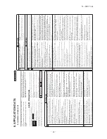
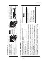
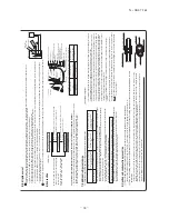
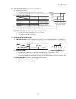
1. HAULAGE AND INSTALLATION
(Take particular care in carrying in or moving the unit, and always perform such an operation with two or more persons.)
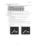
Intake
The
height
of
a
wall
is
1200mm
or
less.
(
service space
)
Intake
Outlet
CAUTION
When
a
unit
is
hoisted
with
slings
for
haulage,
take
into
consideration
the
offset
of
its
gravity
center
position.
If
not
properly
balanced,
the
unit
can
be
thrown
off-balance
and
fall.
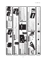
1)
Delivery
2)
Portage
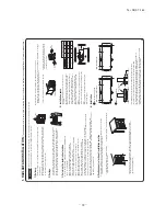
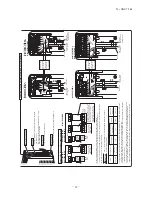
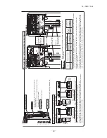
3)
Selecting
the
installation
location
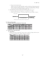
5)
Installation
space
L
3
L
2
L
4
L
1
Model 40, 50, 60
Example
installation
Size
L1
L2
L3
L4
Open
100
100
250
280
75
80
Open
280
Open
80
250
180
Open
80
Open
(mm)
I
II
II
I
IV
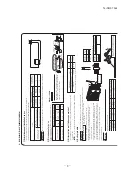
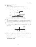
6)
Installation
Pad
Over
500mm
•
Deliver
the
unit
as
close
as
possible
to
the
installation
site
before
removing
it
from
the
packaging.
•
When
you
have
to
unpack
the
unit
for
a
compelling
reason
before
you
haul
it
to
the
installation
point,
hoist
the
unit
with
nylon
slings
or
ropes
and
protection
pads
so
that
you
may
not
damage
the
unit.
•
The
right
hand
side
of
the
unit
as
viewed
from
the
front
(diffuser
side)
is
heavier.
A
person
carrying
the
right
hand
side
must
take
heed
of
this
fact.
A
person
carrying
the
left
hand
side
must
hold
with
his
right
hand
the
handle
provided
on
the
front
panel
of
the
unit
and
with
his
left
hand
the
corner
column
section.
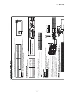
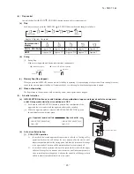
(1)
If the unit is installed in the area where the snow will accumulate, following measures are required. The bottom plate of unit and intake, outlet may be blocked by snow.
1
Install the unit on the base so that the bottom is higher than snow cover surface.
Since drain water generated by defrost control may freeze, following measures are required. •
Do not execute drain piping work by using a drain elbow and drain grommets (accessories). [Refer to Drain piping work.]
2
Install the unit under or provide the roof on site.
Be
sure
to
select
a
suitable
installation
place
in
consideration
of
following
conditions.
•
A
place
where
it
is
horizontal,
stable
and
can
endure
the
unit
weight
and
will
not
allow
vibration
transmittance
of
the
unit.
•
A
place
where
it
can
be
free
from
possibility
of
bothering
neighbors
due
to
noise
or
exhaust
air
from
the
unit.
•
A
place
where
the
unit
is
not
exposed
to
oil
splashes.
•
A
place
where
it
can
be
free
from
danger
of
flammable
gas
leakage.
•
A
place
where
drain
water
can
be
disposed
without
any
trouble.
•
A
place
where
the
unit
will
not
be
affected
by
heat
radiation
from
other
heat
source.
•
A
place
where
snow
will
not
accumulate.
•
A
place
where
the
unit
can
be
kept
away
5m
or
more
from
TV
set
and/or
radio
receiver
in
order
to
avoid
any
radio
or
TV
interference.
•
A
place
where
good
air
circulation
can
be
secured,
and
enough
service
space
can
be
secured
for
maintenance
and
service
of
the
unit
safely.
•
A
place
where
the
unit
will
not
be
affected
by
electromagnetic
waves
and/or
high-harmonic
waves
generated
by
other
equipment.
•
A
place
where
chemical
substances
like
sulfuric
gas,
chloric
gas,
acid
and
alkali
(including
ammonia),
which
can
harm
the
unit,
will
not
be
generated
and
not
remain.
•
If
a
operation
is
conducted
when
the
outdoor
air
temperature
is
-5
lower,
the
outdoor
unit
should
be
installed
at
a
place
where
it
is
not
influenced
by
natural
wind.
•
A
place
where
strong
wind
will
not
blow
against
the
outlet
air
blow
of
the
unit.
4) Caution about selection of installation location
•
Walls surrounding the unit in the four sides are not acceptable.
•
There must be a 1-meter or larger space in the above.
•
When more than one unit are installed side by side, provide a 250mm or wider interval between them as a service space. In order to facilitate servicing of controllers, please provide a sufficient space between units so that their top plates can be removed easily.
•
Where a danger of short-circuiting exists, install guide louvers.
•
When more than one unit are installed, provide sufficient intake space consciously so that short-circuiting may not occur.
•
Where piling snow can bury the outdoor unit, provide proper snow guards.
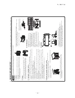
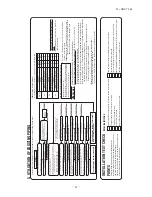
1
Anchor
bolt
fixed
position
Fasten
with
bolts
(M10-12)
Use
a
thicker
block
to
anchor
deeper.
Use
a
long
block
to
extend
the
width.
•
In installing the unit, fix the unit’s legs with bolts specified on the above.
•
The protrusion of an anchor bolt on the front side must be kept within 15mm.
•
Securely install the unit so that it does not fall over during earthquakes or strong winds, etc.
•
Refer to the above illustrations for information regarding concrete foundations.
•
Install the unit in a level area. (With a gradient of 5mm or less.) Improper installation can result in a compressor failure, broken piping within the unit and abnormal noise generation.
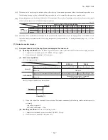
2
Notabilia
for
installation
(2)
If the unit can be affected by strong wind, following measures are required. Strong wind can cause damage of fan (fan motor), or can cause performance degradation, or can trigger anomalous stop of the unit due to rising of high pressure.
1
Place
the
unit
outlet
side
is
turned
to
the
wall
.
2
Install
so
the
direction
of
the
air
from
the
blowing
outlet
will
be
perpendicular
to
the
direction
of
the
wind.
Over
500mm
Heavy
Wind direction
Wind direction
Intake
Outlet
312.5
24.3
14.8
290
89
510
201
351.6
Summary of Contents for SRF25ZMXA-S
Page 2: ......
Page 3: ... 14 SRF T 163 TECHNICAL MANUAL ...
Page 12: ... 10 14 SRF T 163 3 Remote control Unit mm 60 26 167 a Wireless remote control ...
Page 93: ... 91 14 SRF T 163 WARING CAUTION 3 Super link E board SC ADNA E F ...
Page 94: ... 92 14 SRF T 163 ...
Page 100: ... 98 14 SRF T 163 CRCE0010 12 13 14 3 2 1 4 4 5 10 10 4 7 8 9 6 15 16 11 CONTROL PARTS SET ...
Page 106: ... 104 14 SRF T 163 CRCE0010 12 13 14 3 2 1 4 4 5 10 10 4 7 8 9 6 15 16 11 CONTROL PARTS SET ...
Page 112: ... 110 14 SRF T 163 CRCE0010 12 13 14 3 2 1 4 4 5 10 10 4 7 8 9 6 15 16 11 CONTROL PARTS SET ...
Page 114: ... 112 14 SRF T 163 CRBE0276 6 13 11 12 15 16 3 17 14 2 4 9 8 7 5 1 8 8 10 PANEL FAN ASSY ...
Page 118: ... 116 14 SRF T 163 CRBE0276 6 13 11 12 15 16 3 17 14 2 4 9 8 7 5 1 8 8 10 PANEL FAN ASSY ...
Page 122: ... 120 14 SRF T 163 CRBE0315 9 13 15 16 14 17 7 6 4 1 8 3 11 5 18 10 10 10 2 12 PANEL FAN ASSY ...