


-
22
-
'14 • SRK-T-170
RYD012A245
WALL TYPE AIR CONDITIONER
R410A REFRIGERANT USED
WARNING
• Installation must be carried out by the qualified installer.
If you install the system by yourself, it may cause serious trouble such as water leaks,
electric shocks, fire and personal injury, as a result of a system malfunction. Do not carry
out the installation and maintenance work except by the qualified installer.
• Install the system in full accordance with the installation manual.
Incorrect installation may cause bursts, personal injury, water leaks, electric shocks and fire.
• Be sure to use only for household and residence.
If this appliance is installed in inferior environment such as machine shop etc., it can
cause malfunction.
• Use the original accessories and the specified components for installation.
If parts other than those prescribed by us are used, It may cause water leaks, electric
shocks, fire and personal injury.
• Install the unit in a location with good support.
Unsuitable installation locations can cause the unit to fall resulting in material damage
and personal injury.
• Ensure the unit is stable when installed, so that it can withstand
earthquakes and strong winds.
Unsuitable installation locations can cause the unit to fall and cause material damage and
personal injury.
• Ventilate the working area well in the event of refrigerant leakage during
installation.
If the density of refrigerant exceeds the limit, please consult the dealer and install the
ventilation system, otherwise lack of oxygen can occur, which can cause serious
accident.
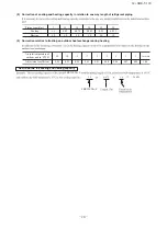
• When installing in small rooms, take prevention measures not to exceed
the density limit of refrigerant in the event of leakage, referred by the
formula (accordance with ISO5149).
If the density of refrigerant exceeds the limit, please consult the dealer and install the
ventilation system, otherwise lack of oxygen can occur, which can cause serious accident.
• After completing installation, check that no refrigerant leaks from the system.
If refrigerant leaks into the room and comes into contact with an oven or other hot
surface, poisonous gas is produced.
• Use the prescribed pipes, flare nuts and tools for R410A.
Using existing parts (for R22 or R407C) can cause the unit failure and serious accidents
due to burst of the refrigerant circuit.
• Tighten the flare nut by torque wrench with specified method.
If the flare nuts were tightened with excess torque, this may cause burst and refrigerant
leakage after a long period.
• Do not open the operation valves for liquid line and gas line until
completed refrigerant piping work, air tightness test and evacuation.
If the compressor is operated in state of opening operation valves before completed
connection of refrigerant piping work, air can be sucked into refrigerant circuit, which can
cause burst or personal injury due to anomalously high pressure in the refrigerant.
• The electrical installation must be carried out by the qualified electrician in
accordance with “the norm for electrical work” and “national wiring
regulation”, and the system must be connected to the dedicated circuit.
Power supply with insufficient capacity and incorrect function done by improper work
can cause electric shocks and fire.
• Be sure to shut off the power before starting electrical work.
Failure to shut off the power can cause electric shocks, unit failure or incorrect function
of equipment.
• Be sure to use the cables conformed to safety standard and cable ampacity
for power distribution work.
Unconformable cables can cause electric leak, anomalous heat production or fire.
• This appliance must be connected to main power supply by means of a circuit
breaker or switch (fuse:16A) with a contact separation of at least 3mm.
• When plugging this appliance, a plug conforming to the norm IEC60884-1
must be used.
• Use the prescribed cables for electrical connection, tighten the cables
securely in terminal block and relieve the cables correctly to prevent
overloading the terminal blocks.
Loose connections or cable mountings can cause anomalous heat production or fire.
• Arrange the wiring in the control box so that it cannot be pushed up further
into the box. Install the service panel correctly.
Incorrect installation may result in overheating and fire.
• Be sure to fix up the service panels.
Incorrect fixing can cause electric shocks or fire due to intrusion of dust or water.
• Be sure to switch off the power supply in the event of installation,
inspection or servicing.
If the power supply is not shut off, there is a risk of electric shocks, unit failure or
personal injury due to the unexpected start of fan.
• Stop the compressor before removing the pipe after shutting the service
valve on pump down work.
If the pipe is removed when the compressor is in operation with the service valve open,
air would be mixed in the refrigeration circuit and it could cause explosion and injuries
due to abnormal high pressure in the cooling cycle.
• Only use prescribed option parts. The installation must be carried out by
the qualified installer.
If you install the system by yourself, it can cause serious trouble such as water leaks,
electric shocks, fire.
• Be sure to wear protective goggles and gloves while at work.
• Earth leakage breaker must be installed.
If the earth leakage breaker is not installed, it can cause electric shocks.
• Do not put the drainage pipe directly into drainage channels where
poisonous gases such as sulphide gas can occur.
Poisonous gases will flow into the room through drainage pipe and seriously affect the
user’s health and safety. This can also cause the corrosion of the indoor unit and a
resultant unit failure or refrigerant leak.
• Ensure that no air enters in the refrigerant circuit when the unit is installed
and removed.
If air enters in the refrigerant circuit, the pressure in the refrigerant circuit becomes too
high, which can cause burst and personal injury.
• Do not process or splice the power cord, or share the socket with other
power plugs.
This may cause fire or electric shock due to defecting contact, defecting insulation and
over-current etc.
• Do not bundle or wind or process the power cord. Do not deform the power
cord by treading it.
This may cause fire or heating.
• Do not vent R410A into the atmosphere : R410A is a fluorinated greenhouse
gas, covered by the Kyoto Protocol with Global Warming Potential (GWP)=1975.
• Do not run the unit with removed panels or protections.
Touching rotating equipments, hot surfaces or high voltage parts can cause personal
injury due to entrapment, burn or electric shocks.
• Do not perform any change of protective device itself or its setup condition.
The forced operation by short-circuiting protective device of pressure switch and
temperature controller or the use of non specified component can cause fire or burst.
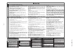
SAFETY PRECAUTIONS
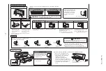
• Before installation, read the “SAFETY PRECAUTIONS” carefully and strictly follow it during the installation work in
order to protect yourself.
• The precautionary items mentioned below are distinguished into two levels, and .
: Wrong installation would cause serious consequences such as injuries or death.
: Wrong installation might cause serious consequences depending on circumstances.
Both mention the important items to protect your health and safety so strictly follow them by any means.
• Be sure to confirm no anomaly on the equipment by commissioning after completed installation and explain the oper-
ating methods as well as the maintenance methods of this equipment to the user according to the owner’s manual.
• Keep the installation manual together with owner’s manual at a place where any user can read at any time.
Moreover if necessary, ask to hand them to a new user.
• Before starting the installation work, proper precautions (using suitable protective clothing, groves etc.) should be
taken by qualified installer.
• Please pay attention not to fall down the tools, etc. when installing the unit at the high position.
• If unusual noise can be heard during operation, consult the dealer.
• The meanings of “Marks” used here are shown as follows:
CAUTION
WARNING
CAUTION
WARNING
Never do it under any
circumstances.
Always do it according to the
instruction.
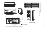
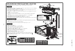
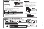
• While install the unit, be sure to check the selection of installation place,
power supply specifications, usage limitation (piping length, height
d
ifferences
between in
d
oor an
d
out
d
oor units, power supply voltage etc.) an
d
installation
spaces.
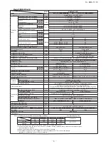
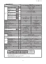
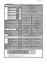
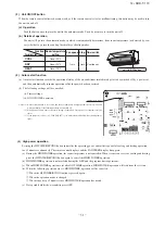
8. APPLICATION DATA
Models SRK25ZXA-S/SB/SS/SR, 35ZXA-S/SB/SS/SR