


-
55
-
◆
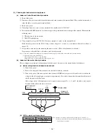
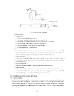
Inspection of resistance v
alue of disc
har
g
e
pipe
sensor
Remove the connector and check the resistance value.
See the section of sensor characteristics on page 48.
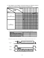
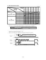
◆
Inspection of electr
onic e
xpansion v
alve
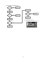
T
o
test if there is v
olta
g
e
.
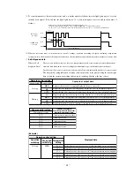
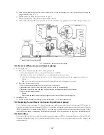
◆
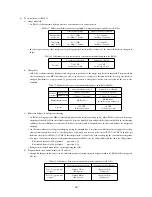
Chec
k point of outdoor unit (50 type)
If the e
xpansion v
alve does not operate as sho
wn abo
ve
, it is def
ective
.
(V
oltage is only applied to the electronic expansion valve when the valve opening
is being changed.)
Red to
White
Red to Orange
Brown to
Y
ellow
Brown to Blue
Normal if there is approximately DC 5
V
10 seconds
after the power asupply is turned on.
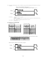
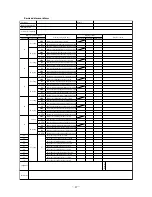
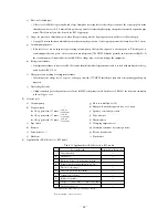
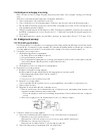
◆
Inspection of input to PCB
¡
Check the voltage between terminals
1
~
2
on the terminal block.
(It is
normal if
AC 220/230/240V
is detected.)
◆
Inspection of serial signal
Check the voltage between terminals
2
~
3
on the terminal block.(It is normal
if the needle swing in the range of DC
0~Approx.12V)
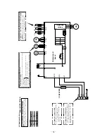
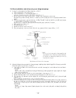
CA
UTION
-
HIGH
V
O
L
T
A
GE
High voltage is produced in the control box. Don
t touch
electrical parts in the control box for 5 minutes after the
unit is stopped.
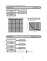
Black
Brown
Red
Blue
White
Yellow/Green
BK
BR
RD
BL
Orange
OR
Green
GR
WH
Y/GN
Color symbol
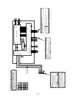
N_1
P_1
BK
RD
N_1
P_1
DC-N
DC-P
PWB3 (CAPACITOR)
BK
RD
CNG
PWB1 (MAIN )
PWB2 (POWER )
EEV
Th4
Th5
Th6
CNT
CNJ
CND
CNB
FMo
20S
F(250V 15A)
BK
1
L-1
AC.N
AC.L
AC.N
AC.L
BL
GR
BL
GR
L
AF_L2
AF_L1
OR
OR
V
CM
W
BK
RD
WH
OR
OR
BK
RD
WH
U
CNH
CNG
CNH
CNG
G3
RD
Y/GN
CNI
WH
2
N-1
3
CNO.1