


-
206
*
-
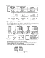
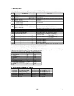
7-2. Selection of controls
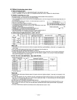
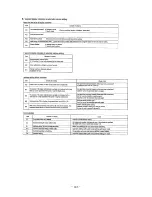
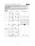
7-3. External input and output terminals specifications
Setting value for allocation of external input function
Name
Purpose (Factory default)
Specification
Operating side connector
With external input terminals closed With external input terminals opened
Invalid
Invalid
Valid
Valid
Valid
Test run start
Cooling
Valid
External input CnS1
External input CnS2
External input CnH1
External input CnG2
External output CnH
External output CnY
External operation input (Closed at shipping)
Demand input (Closed at shipping)
Cooling / Heating forced input (Opened at shipping)
Silencing mode input (Opened at shipping)
Operation output
Error output
Non-voltage contactor (DC12V)
Non-voltage contactor (DC12V)
Non-voltage contactor (DC12V)
Non-voltage contactor (DC12V)
DC12V output
DC12V output
NICHIATSU B02B-XAMK-1 (LF) (SN)
NICHIATSU B02B-XARK-1 (LF) (SN)
NICHIATSU B02B-XAEK-1 (LF) (SN)
NICHIATSU B02B-XASK-1 (LF) (SN)
MOLEX 5286-02A-BU
MOLEX 5266-02A
Valid
Valid
Invalid
Invalid
Invalid
Normal
Heating
Invalid
"0" : External operation input
"1" : Demand input
"2" : Cooling/heating forced input
"3" : Silent mode input
"4" : Spare
"5" : Outdoor fan snow guard control input
"6" : Test run external input 1 (equivalent to SW5-1)
"7" : Test run external input 2 (equivalent to SW5-2)
"8" : Silent mode 2
"9" : Spare
Controls of outdoor unit may be selected as follows using the dip switches on the PCB and C
○○
, P
○○
on the 7-segment.
To change C
○○
, P
○○
on the 7-segment, hold down SW8 (7-segement display increment up: 1-digit), SW9 (7-segment increment up: 10-digit) and SW7 (Data write/Enter).
By changing the allocation of external input functions (P11
〜1
4) on the 7-segment, functions of external
input terminals may be selected. Inputting signals to external input terminals enable the following functions.
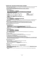
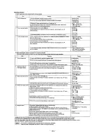
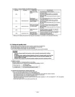
Control selecting method
Content of control
SW setting on PCB
SW5-5
C
○○
,
P
○○
on 7-segment
SW3-7 to ON *2
SW3-2 to ON
SW5-1 to ON + SW5-2 to OFF Heating test run
High static pressure mode
SW5-1 to ON + SW5-2 to ON
Cooling test run
Communication method selection ON: Previous SL communication, OFF: New SL communication
J13: Closed (Factory default), J13: Opened External input selection (CnS1, CnS2 only) Closed: Level input, Opened: Pulse input
J15: Closed (Factory default), J15: Opened
Defrost selection Closed: Normal defrosting, Opened: Forced defrosting
Allocation of external input (CnS1)
Allocation of external input (CnS2)
Allocation of external input (CnG1)
Allocation of external input (CnG2)
Outdoor unit fan snow protection control ON time setting - 30 sec (at shipping) 10, 30-600 sec
Pump down operation
Operation priority selection
SW4-5:OFF, SW4-6:OFF*2 80% (Factory default)
SW4-5:ON , SW4-6:OFF*2 60%
SW4-5:OFF, SW4-6:ON*2 40%
SW4-5:ON , SW4-6:ON*2 00%
ー
ー
ー
ー
ー
ー
ー
ー
ー
ー
ー
ー
ー
ー
ー
Close the fluid operation valve on outdoor unit and set as follows:
(1) SW5-2 on PCB to ON
(2) SW5-3 on PCB to ON
(3) SW5-1 on PCB to ON
Forced cooling mode
(It can be fixed at cooling with external input terminals opened, or at heating with them closed.)
Automatic back up operation
Set external input function
allocation to
"2"
*2
Set allocation of external
allocation to
"1"
*2
Inputting signals to external input terminals selects the demand mode.
(J13 short-circuited: Level input, J13 open: Pulse input)
0: First push priority (at shipping)
1: Last push priority
Outdoor unit fan snow protection control 0: Control disabled (at shipping)
1: Control enabled
C70
C75
P11
P12
P13
P14
P16
J14
: Closed (Factory default), J14: Opened
※
1 "Unit set" shown in the above table refers to the master/slave
setting of units comprising a combined installation.
Master: control mode setting required for the master unit only (setting not required with the slave unit).
Master/slave: control mode setting required for both master and slave units.
※
2
Control is switched when both the allocation of external input function (P11
〜
14) and SW are changed.
(Example: To use CnS1 for the input of forced cooling mode, set P11 at 2 and SW3-7 at ON. To use CnS2 for the input of forced cooling mode, set P12 at 2 and SW3-7 at ON.)
Defrosting mode is switched. (will enter defrosting mode more frequently)
Master
Master
Master
Master
Master
Master
Master
Master
Master
Master/slave
Master/slave
Master/slave
SW6-3 to ON
Master/slave
Master/slave
Unit set
※
1
Summary of Contents for FDE112KXE6A
Page 104: ... 102 ...
Page 111: ... 108 b Ceiling cassette 4 way Compact type FDTC Models All moddels B PJA003Z331 ...
Page 112: ... 109 c Ceiling cassette 2 way type FDTW Models FDTW28KXE6 45KXE6 56KXE6 B PJB001Z560 ...
Page 113: ... 110 Models FDTW71KXE6 90KXE6 B PJB001Z561 ...
Page 114: ... 111 Models FDTW112KXE6 140KXE6 B PJB001Z562 ...
Page 115: ... 112 d Ceiling cassette 1 way type FDTS Model FDTS45KXE6 A PJC001Z195 ...
Page 116: ... 113 Model FDTS71KXE6 A PJC001Z196 ...
Page 117: ... 114 e Ceiling cassette 1 way compact type FDTQ Models All models A PJC001Z190 ...
Page 118: ... 115 Models All models Duct panel A PJC001Z240 ...
Page 121: ... 118 Models FDU224KXE6 280KXE6 B PJD001Z230 ...
Page 123: ... 120 Models FDUM112KXE6 140KXE6 B PJR002Z259 ...
Page 124: ... 121 h Duct connected Ultra thin Low static pressure type FDQS Models All models C PJC001Z200 ...
Page 125: ... 122 i Wall mounted type FDK Models FDK22KXE6 28KXE6 36KXE6 45KXE6 56KXE6 B PHA000Z983 ...
Page 126: ... 123 Models FDK71KXE6 B PHA000Z984 ...
Page 127: ... 124 j Ceiling suspended type FDE Models FDE36KXE6A 45KXE6A 56KXE6A B PFA003Z826 ...
Page 128: ... 125 Models FDE71KXE6A 112KXE6A 140KXE6A B PFA003Z827 ...
Page 129: ... 126 k Floor standing with casing type FDFL Models All models B PGD000Z053 ...
Page 130: ... 127 l Floor standing without casing type FDFU Models All models A PGD000Z058 ...
Page 131: ... 128 m Duct Connected Compact and Flexible type FDUH Models All models A PJC001Z255 ...
Page 138: ... 135 ...
Page 139: ... 136 ...
Page 143: ... 140 b ...
Page 144: ... 141 ...
Page 191: ... 188 5 4 Installation of outdoor unit ...
Page 193: ... 190 ...
Page 194: ... 191 ...
Page 195: ... 192 ...
Page 196: ... 193 ...
Page 197: ... 194 ...
Page 198: ... 195 ...
Page 199: ... 196 ...
Page 200: ... 197 ...
Page 201: ... 198 ...
Page 202: ... 199 ...
Page 203: ... 200 ...
Page 204: ... 201 ...
Page 205: ... 202 ...
Page 206: ... 203 ...
Page 207: ... 204 ...
Page 208: ... 205 ...
Page 210: ... 207 ...
Page 211: ... 208 ...
Page 212: ... 209 ...
Page 215: ... 212 2 model type DIS model type HEAD ...
Page 216: ... 213 2 2 ...
Page 217: ... 214 2 2 2 2 2 ...