


Page 21
MODELS: WS-48511 / WS-55511 / WS-55711 / WS-65511 / WS-65611 / WS-65711 / WS-65712 / WS-73711 / WS-B55
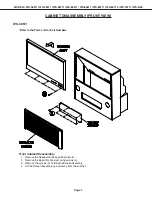
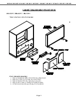
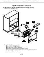
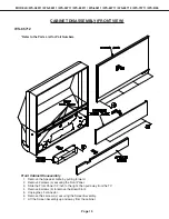
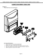
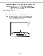
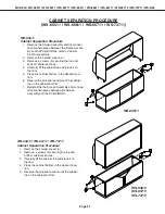
CABINET SEPARATION PROCEDURE
(WS-65511 / WS-65611 / WS-65711 / WS-73711)
WS-65511
Cabinet Separation Precedure
1.
Remove the Screen Assembly and disconnect
all cable harnesses between the Frame Assem-
bly and the PCB-SIGNAL, refer to Cabinet
Front Disassembly.
2.
Remove the 4 screw covers (a).
3.
Remove 4 screws (b) securing the top and
bottom cabinet sections .
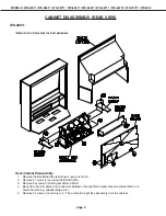
4.
Carefully lift the cabinet top and place it on
the floor.
5.
Place the cabinet bottom in the desired loca-
tion.
6.
Reverse the procedure and mount the cabinet
top on the cabinet bottom.
7.
Reinstall the the Screen Assembly and connect
all cable harnesses between the Screen
Assembly and the PCB-SIGNAL.
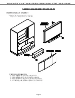
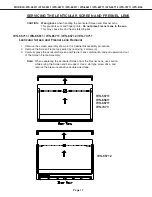
WS-65611
WS-65711
WS-73711
WS-65611 / WS-65711 / WS-73711
Cabinet Separation Precedure
1.
Remove the 4 screw covers (a).
2.
Remove 4 screws (b) securing the top and
bottom cabinet sections .
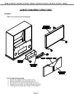
3.
Carefully lift the cabinet top and place it on
the floor.
4.
Place the cabinet bottom in the desired loca-
tion.
5.
Reverse the procedure and mount the cabinet
top on the cabinet bottom.
WS-65511