background image

EN-13

Viewing computer images

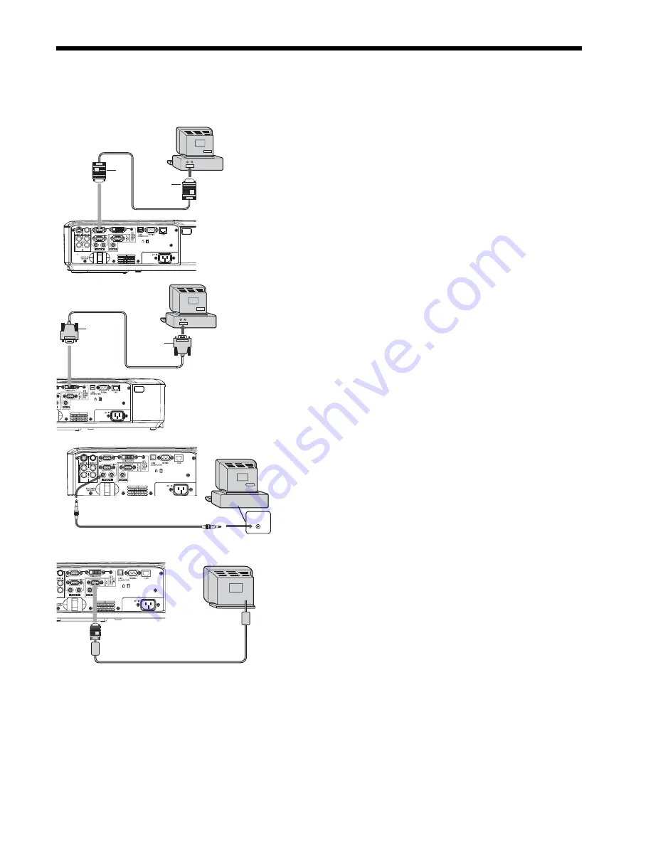
A. Connecting the projector to a computer

Preparation: 

•  Make sure that the power of the projector and that of the computer are turned off. 
•  When connecting the projector to a desktop computer, disconnect the RGB cable that is connected to the monitor. 

For analog connection: 

1.  Connect one end of the supplied RGB cable to the 

COMPUTER/COMPONENT VIDEO IN-1/IN-2 terminal of 
the projector. 

2.  Connect the other end of the RGB cable to the monitor 

port of the computer.

•  Additional devices, such as a conversion connector and an 

analog RGB output adapter, are required depending on the 
type of the computer to be connected.

For monitor connection: 

1.  Connect the RGB cable from the monitor to the MONITOR 

OUT terminal of the projector. 

COMPUTER/COMPONENT 
VIDEO IN-1/IN-2

COMPUTER/COMPONENT 
VIDEO DVI-D (HDCP)

To monitor port

RGB cable

DVI cable
(option)

To DVI

AUDIO OUT 

AUDIO IN-1/IN-2 

Computer

PC audio cable (option)

To PC audio
output

MONITOR OUT

Monitor

•  Use of a long cable may decrease the quality of projected images. 
•  Images may not be projected correctly, depending on the type of the connected computer. 
•  Also read the instruction manual of the equipment to be connected. 
•  Contact your dealer for details of connection.

For digital connection: 

1.  Connect one end of a commercially available DVI cable 

to the COMPUTER/COMPONENT VIDEO DVI-D (HDCP) 
terminal of the projector. 

2.  Connect the other end of the DVI cable to the DVI terminal 

of the computer. 

For audio connection: 

•  This projector uses stereo pin jack for its audio input. Check 

the type of the audio output terminal of the connected 
computer and prepare a proper cable for connection. Some 
computers don’t have the audio output terminal.

•  When the audio cable is connected to the AUDIO OUT ter-

minal, the speaker output is muted.

Computer

Computer

RGB cable

Summary of Contents for WL2650U

Page 1: ...WL2650 LCD PROJECTOR MODEL WL2650U User Manual This User Manual is important to you Please read it before using your projector ...

Page 2: ...the attached specified power supply cord If you use another power supply cord it may cause interference with radio and television reception Use the attached RGB cable and RS 232C cable and the shielded LAN cable with this equipment so as to keep interference within the limits of a FCC Class B device This apparatus must be grounded DO NOT LOOK DIRECTLY INTO THE LENS WHEN THE PROJECTOR IS IN THE POWE...

Page 3: ...any interference received including interference that may cause undesired operation Note This symbol mark is for EU countries only This symbol mark is according to the directive 2002 96 EC Article 10 Information for users and Annex IV and or to the directive 2006 66 EC Article 20 Information for end users and Annex II Your MITSUBISHI ELECTRIC product is designed and manufactured with high quality ...

Page 4: ...ids Never push objects of any kind through openings of this projector as they may touch dangerous voltage points or short out parts that could result in a fire or electric shock Never spill liquid of any kind on the projector 14 Servicing Do not attempt to service this projector by yourself Refer all servicing to qualified service personnel 15 Damage requiring service Unplug this projector from the ...

Page 5: ...n lead to breakdown or other failure Place of installation For safety s sake refrain from setting the projector at any place subjected to high temperature and high humidity Please maintain an operating temperature humidity and altitude as specified below Operating temperature between 41 F 5 C and 95 F 35 C Operating humidity between 30 and 90 Never put any heat producing device under the projector ...

Page 6: ...losion Only Carbon Zinc or Alkaline Manganese Dioxide type batteries should be used Dispose of used batteries according to your local regulations Batteries may explode if misused Do not recharge disassemble or dispose of them in fire Be sure to handle the batteries according to the instructions Load the batteries with its positive and negative sides correctly oriented as indicated on the remote con...

Page 7: ...1 10 9 8 Important While the menu or the screen for the keystone adjustment or password entry is being displayed or image captur ing is being executed the COMPUTER VIDEO AUTO POSITION and VOLUME buttons function as the and buttons respectively While the menu is on the screen the KEYSTONE button functions as the ENTER button 1 COMPUTER COMPONENT VIDEO IN 1 terminal Mini D SUB 15 pin 2 COMPUTER COMP...

Page 8: ...he LASER button again You can disable the LASER button to prevent laser radiation due to misuse of the button How to disable the LASER button While holding the LASER button down press the button 3 times How to enable the LASER button While holding the LASER button down press the button 3 times Whenever the batteries are replaced the LASER button is enabled About the laser beam This remote control ...

Page 9: ...e unstable When you use the remote control too close to the remote control sensor the remote control may not work correctly Reception angle Vertical directions Vertical directions ceiling mount Front of projector Rear of projector Operate the remote control within a distance of 10 m 30 feet from the projector pointing the light beam at the remote control photo sensor front or rear of the projector...

Page 10: ...stment foot for the vertical position back into the projector Adjustment of the horizontal position of the projector Adjust the horizontal position of the projector with the adjustment foot for the horizontal position on the bottom Adjustment foot for the vertical position Screen Important Don t transport the projector with its adjustment feet extended Otherwise the adjustment feet may be damaged ...

Page 11: ...the projector at least 50 cm or 20 inches away from the wall to prevent the air inlet grille and the air outlet grilles that emit hot air from being blocked Do not use the projector in the following locations and manners which may cause fire or electric shock In a dusty or humid place In a sideways position or with the lens facing down Near a heater In an oily smoky or damp place such as a kitchen ...

Page 12: ... 3 8 300 762 159 404 254 646 379 9 6 3 9 10 40 102 24 61 32 81 18 46 32 81 3 0 8 46 1 2 56 1 4 0 5 1 60 152 36 91 48 122 27 69 48 122 4 5 11 70 1 8 85 2 2 0 8 2 80 203 48 122 64 163 36 91 64 163 6 0 15 94 2 4 114 2 9 1 0 3 100 254 60 152 80 203 45 114 80 203 7 5 19 118 3 0 143 3 6 1 3 3 150 381 90 229 120 305 68 171 120 305 11 3 29 178 4 5 215 5 5 1 9 5 200 508 120 305 160 406 90 229 160 406 15 0 ...

Page 13: ...VIDEO DVI D HDCP To monitor port RGB cable DVI cable option To DVI AUDIO OUT AUDIO IN 1 IN 2 Computer PC audio cable option To PC audio output MONITOR OUT Monitor Use of a long cable may decrease the quality of projected images Images may not be projected correctly depending on the type of the connected computer Also read the instruction manual of the equipment to be connected Contact your dealer ...

Page 14: ...ay cause fire or electric shock Do not modify or alter the power cord If the power cord is modified or altered it may cause fire or electric shock Caution Plug in the power cord firmly When unplugging hold and pull the power plug not the power cord Do not plug in or out the power cord with your hand wet It may cause electric shock 2 1 Earthing terminal Power cord example Viewing computer images contin...

Page 15: ... D HDCP button on the remote control that is corresponding to the terminal in use The input source is switched from COMPUTER1 to COMPUTER2 to DVI at every press of the COMPUTER button on the projector The projector automatically selects the appropriate signal format The selected signal format is displayed on the screen The COMPUTER COMPUTER 1 COMPUTER 2 and DVI D HDCP buttons don t function while ...

Page 16: ... The video and audio signals are temporarily muted when the MUTE button is pressed To cancel muting press the MUTE button again It takes several seconds before muting is completely canceled If MUTE MODE in the INSTALLATION menu is set to IMAGE the splash screen will appear when the MUTE button is pressed You can alter the splash screen optionally See page 32 The audio from the AUDIO OUT terminal i...

Page 17: ...hat are not being received enabled When the video equipment is equipped with the S video output terminal make the connection as follows 1 Connect one end of a commercially available S video cable to the S VIDEO IN terminal of the projector 2 Connect the other end of the S video cable to the S video output terminal of the video equipment 3 Connect one end white and red of the supplied audio video c...

Page 18: ...ovided with a function to switch the methods to output DVI digital signals When your DVD player is provided with such function set it as follows EXPAND or ENHANCED o NORMAL See the users guide of your DVD player for details When your digital device does not have such function adjust the BRIGHTNESS to 16 and CONTRAST to 17 in the IMAGE menu of this projector or adjust the black color by viewing the...

Page 19: ...utton on the projector or the VIDEO or S VIDEO button on the remote control that is corresponding to the terminal in use The input source is switched between VIDEO and S VIDEO at every press of the VIDEO button on the projector The VIDEO and S VIDEO buttons don t function while the menu is being displayed Though it may take some time before an image is displayed on the screen depending on the type...

Page 20: ...t If the power cord should be unplugged accidentally while either the air inlet fan or the air outlet fans are oper ating or the lamp is on allow the projector to cool down for 10 minutes with the power off To light the lamp again press the POWER button If the lamp doesn t light up immediately repeat pressing the POWER button 2 or 3 times If it should still fail to light up replace the lamp Cover ...

Page 21: ... the or button Important You can correct the vertical and horizontal keystones at the same time However their adjustment ranges are limited in such correction When the keystone adjustment is carried out the adjustment value is indicated Note that this value doesn t mean a projection angle The allowable range of the adjustment value in the keystone adjustment varies depending on the installation co...

Page 22: ...aliano SIGNAL INFORMATION MEMORY CALL HOLD SETUP AUTO MEMORY 1 MEMORY 2 RESOLUTION MEMORIZE Horizontal Pixels x Vertical Lines FINE SYNC 0 31 TRACKING USER 0 9999 CLAMP POSITION 1 255 CLAMP WIDTH 1 63 LPF ON OFF OVER SCAN 100 90 SHUTTER L 0 20 SHUTTER U 0 20 SHUTTER RS 0 20 SHUTTER LS 0 20 VERT SYNC AUTO OFF 3 8 2 3 8 3 2 2 2 3 8 3 8 5 AUTO OFF CINEMA MODE 3 8 3 8 3 8 HORIZ POSITION 0 999 VERT POS...

Page 23: ...d TINT 10 Use to adjust the color tint of the projected image See page 28 When the COMPUTER1 COMPUTER2 or DVI is selected as the input source TINT can t be adjusted TINT is available only when the NTSC signal is input SHARPNESS 5 Use to adjust the sharpness of the projected image See page 28 ADVANCED MENU NOISE REDUCTION ON OFF Use to reduce noise and roughness in the image when noisy video signal...

Page 24: ...ound from among BLUE BLACK and IMAGE which will be displayed when there is no signal input from the source When IMAGE is selected the splash screen will be displayed MUTE MODE BLACK IMAGE Use to choose the background either BLACK or IMAGE which will be displayed when the MUTE button is pressed When IMAGE is chosen the splash screen will be displayed IMAGE REVERSE OFF Select when viewing images fro...

Page 25: ...he input signal If the image isn t displayed correctly select the desired video format manually SETUP AUTO Select to change the SETUP mode automatically OFF Select to make black lighter 3 75 7 5 Select to make black thicker When 7 5 is chosen the brightness is decreased by the set up can cel function for the U S Choose OFF when the image is dark SCART INPUT ON OFF Choose ON when connecting the pro...

Page 26: ... OK The process to change the current resolution is canceled and the SIGNAL menu is displayed HORIZ POSITION 0 999 Use to adjust the horizontal position of the projected image VERT POSITION 0 999 Use to adjust the vertical position of the projected image FINE SYNC 0 31 Use to eliminate flickering or blur if appears viewing the projected image TRACKING 0 9999 Use to eliminate vertical wide stripes i...

Page 27: ...g time is 0 to 10 hours 0H is displayed The lamp operating time exceeding 10 hours is indicated by the actual hours When the lamp operating time reaches 3000 hours the bar turns to yellow When it reaches 3800 hours the bar turns to red INPUT Indicates the name of the terminal to which the currently projected video signal is being input RESOLUTION Indicates the resolution of the currently projected...

Page 28: ... 23 for menu setting 1 Display the IMAGE menu 2 Select COLOR or TINT by pressing the or button COLOR or TINT is unavailable when COMPUTER1 COMPUTER2 or DVI is selected as the input source TINT is available only when the NTSC signal is input 3 Adjust the selected item by pressing the or button To cancel the menu 4 Press the MENU button COLOR Use to adjust the color thickness of the projected image ...

Page 29: ...rature Decrease the CONTRAST B blue and increase the CONTRAST R red If you set all of CONTRAST R G and B to negative values the original brightness of the image can t be obtained even when you maximize CONTRAST in the IMAGE menu CONTRAST B 0 BRIGHTNESS R 0 CONTRAST R COLOR TEMP USER 0 CONTRAST G 0 BRIGHTNESS G 0 BRIGHTNESS B 0 Color Enhancer You can set the user defined balance between the brightne...

Page 30: ... the Settings tab to display the screen resolution setting The screen resolution setting of your computer is different from the setting of RESOLUTION MEMORIZE in the SIGNAL menu of the projector Select RESOLUTION MEMORIZE in the SIGNAL menu and press the ENTER button Set HORIZ PIXELS and VERT LINES to the values of the screen resolution of your computer Example When the screen resolution of the co...

Page 31: ... on the right or left half of the image Adjust SHUTTER LS or SHUTTER RS in the SIGNAL USER menu Noise appears on the top or bottom part of the image Adjust SHUTTER U or SHUTTER L in the SIGNAL USER menu 1 Display the SIGNALmenu 2 Press the or button to select an item to adjust 3 Adjust the selected item by pressing the or button To cancel the menu 4 Press the MENU button Do not change the settings...

Page 32: ...0 or BLUE50 by pressing the or button Set the image size 8 Select SIZE by pressing the or button 9 Select x1 x2 or FULL by pressing the or but ton Capture the image 10 Select CAPTURE by pressing the or button 11 Press the ENTER button A red frame appears The size of the red frame is 336 x 210 pixels 12 Adjust the size of the image to be captured so that such image stays within the red frame Press ...

Page 33: ...DISPLAY INPUT MENU ACCESS and SPLASH ID SCREEN When the password has already been set the mode won t be changed In such cases press the ENTER button to cancel the password func tion and try again 4 Press the ENTER button The screen for setting the password function will appear 5 Press the ENTER button The screen for entering a password will appear 6 Enter a 4 8 digit password using the or button o...

Page 34: ...ppear Important In the EXPAND mode you can t adjust the volume Picture in Picture PinP One of the special features of this projector is the picture in picture PinP mode The PinP mode allows you to view the images from different sources at the same time To use the PinP mode 1 Press the PinP button on the remote control When you press the PinP button with the image from the COMPUTER COMPONENT VIDEO ...

Page 35: ...rolled by the remote control correctly To extend the cable length you are recommended to use a repeater COMPUTER VIDEO S VIDEO DVI D HDCP HOME PageUP END PageDOWN AUTO POSITION KEYSTONE 1 2 MENU ENTER LASER R CLICK USB Mouse pointer Use to move the cursor on the image instead of the computer mouse R CLICK button This operates in the same way as the right button on the computer mouse L CLICK button...

Page 36: ...oftware is required For the specifications of PJLink access to the Web site of Japan Business Machine and Information System Industries Association JBMIA http pjlink jbmia or jp english This projector is fully compliant to the specifications of JBMIA PJLink Class 1 It supports all the commands defined by PJLink Class 1 and the compliance has been verified with the PJLink standard specifications Version...

Page 37: ...power was on Lamp operation time warning Total lamp operation time reached 3000 hours 1 while the power was off Lamp operation time warning Total lamp operation time reached 4000 hours 1 2 while the power was off 1 Duration when LAMP MODE of the INSTALLATION menu is set to LOW When it is set to STANDARD this duration will be shorted 2 When LAMP MODE is set to STANDARD this duration will be shorted...

Page 38: ...r about 3800 hours 1 the replacement message LAMP EXCHANGE will appear on the screen for 1 minute every 20 hours 1 thereafter When the lamp operation time exceeds 4000 hours 1 2 the projector automatically shuts off and can t be used until the lamp is replaced and the lamp operation time is reset 1 Duration when LAMP MODE of the INSTALLATION menu is set to LOW When it is set to STANDARD this durat...

Page 39: ... t turn on if the lamp cover isn t attached securely Be sure to reset the lamp operation time whenever you replace the lamp Do not reset the lamp operation time unless you replace the lamp When removing the lamp from the ceiling mounted projector When removing the lamp from the ceiling mounted projector use the lamp replacement tray packed with the projector or option lamp to prevent glass fragmen...

Page 40: ... filter Use water or diluted mild detergent to clean the filter Rinse the filter thoroughly and let it dry completely 4 Attach the air filter 5 Attach the filter cover to the projector Make sure that the air filter is attached correctly without displacement Important If the filter is damaged or becomes extremely dirty change it with a new filter Contact your dealer for a new filter Use the dedicated filter ...

Page 41: ...off Solution Check whether the indicators are on or off and how they are lightning Cancel the AV mute by pressing the MUTE button Check that the lens cap is removed It may take about 1 minute for the lamp to light up The lamp fails to light up on rare occasions In such a case wait for a few minutes and then try again If the projector was turned off before the lamp was cooled down sufficiently last ...

Page 42: ... carried out the image may not be displayed correctly depending on the type of input signal This isn t a product malfunction In this case readjust the keystone so that the amount of keystone correction is as small as possible Check that the cables connected to the external devices are not broken Check that COMPUTER INPUT in the SIGNAL menu is correctly set See page 26 Check that the cable connecte...

Page 43: ...been set to MENU ACCESS to enable the password lock Cancel the password lock or contact the person in charge of management of the projector See page 33 If the following problem occurs after the lamp is replaced check the following first Problem The projector does not turn on The STATUS indicator blinks Solution Fit the lamp cover securely See pages 38 and 39 Reset the lamp operating time See page 3...

Page 44: ...dots Analog compressed Panel resolution 1280 x 800 dots NTSC PAL SECAM 4 43NTSC PAL M PAL N PAL 60 480i 480p 576i 576p 720p 1080i 1080p Panel resolution 1280 x 800 dots Signal type Terminal type Line Analog RGB Mini D SUB 15 pin 2 Digital RGB DVI D 1 Signal type Terminal type Line Video input RCA 1 S Video input S 1 Signal type Terminal type Line RGB Stereo mini jack ø3 5 2 Video RCA L R 1 S video...

Page 45: ...50 750p 50 37 50 50 00 1280 x 720 1 2 1080p 60 1125p 60 67 50 60 00 1280 x 720 1 2 1080p 50 1125p 50 56 25 50 00 1280 x 720 1 2 CGA70 640 x 400 31 47 70 09 1280 x 800 640 x 400 CGA84 640 x 400 37 86 84 13 1280 x 800 640 x 400 CGA85 640 x 400 37 86 85 08 1280 x 800 640 x 400 VGA60 640 x 480 31 47 59 94 1066 x 800 640 x 480 2 VGA72 640 x 480 37 86 72 81 1066 x 800 640 x 480 VGA75 640 x 480 37 50 75 ...

Page 46: ... Pin No Spec DVI D HDCP DVI D 24 pin Pin No Spec Pin No Spec 1 TMDS DATA 2 13 2 TMDS DATA 2 14 5V Power 3 TMDS DATA 2 Shield 15 Ground for 5V 4 16 Hot Plug Detect 5 17 TMDS DATA 0 6 DDC Clock 18 TMDS DATA 0 7 DDC Data 19 TMDS DATA 0 Shield 8 20 9 TMDS DATA 1 21 10 TMDS DATA 1 22 TMDS Clock Shield 11 TMDS DATA 1 Shield 23 TMDS Clock 12 24 TMDS Clock 17 24 16 9 8 1 Connectors 331 333 59 5 113 84 5 2...

Page 47: ...a CHINA Mitsubishi Electric Air Conditioning Visual Information Systems Shanghai Ltd 12 F Hong Kong New World Tower 300 Huaihai Middle Road Shanghai 200021 China Sales Inquiries Phone 86 21 6335 3030 Ext 3007 Fax 86 21 6335 3600 Technical Inquiries Phone 86 21 6335 3030 Ext 3021 Fax 86 21 6335 3600 HONG KONG Mitsubishi Electric Ryoden Air Conditioning Visual Information Systems HongKong Ltd 7th Fl...

Reviews: