background image


Chapter 6. Additional Features 

87

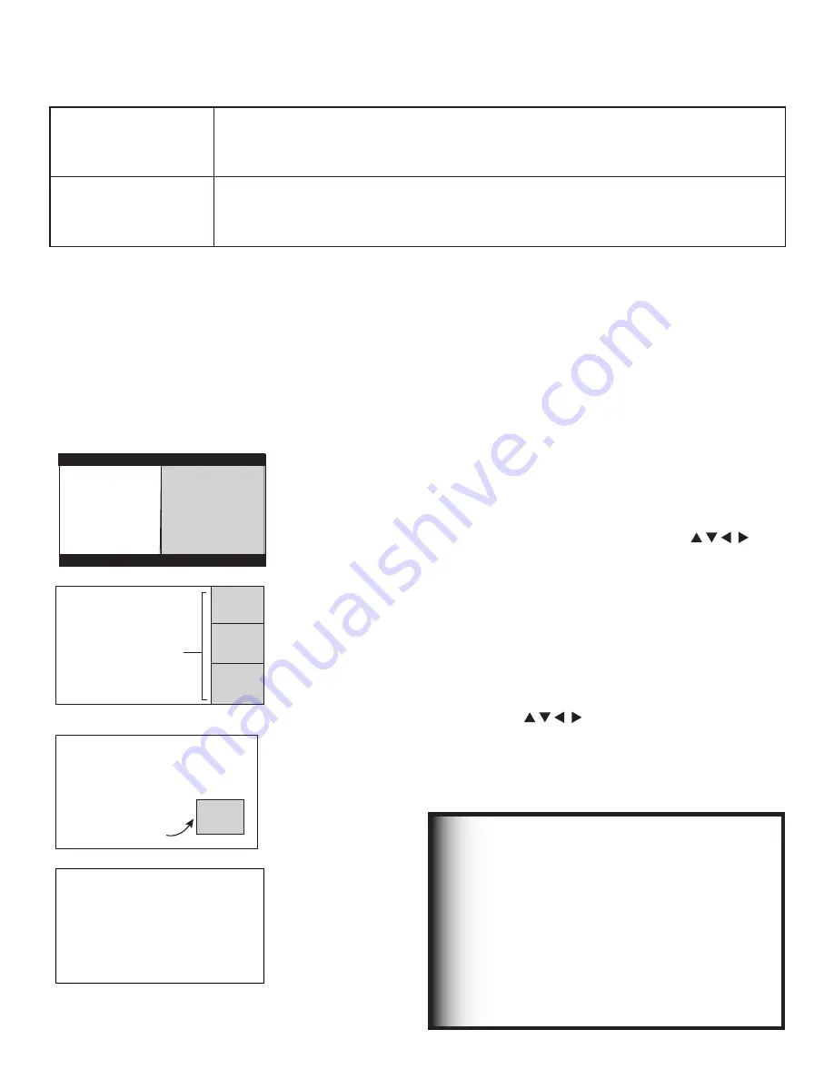
Press PIP/POP to activate the PIP/POP option.  
Repeatedly press the PIP/POP button on the TV remote 
control and within seconds of each press, the PIP/POP 
cycles through the display options below.

To turn PIP/POP off:

•  Press PIP/POP repeatedly until the TV returns to full-

screen mode.

•  Press PIP/POP and wait at least 10 seconds.  Press 

PIP/POP again.  The next time you activate PIP/POP, 
the last-used PIP/POP option will be displayed.

."*/
1*$563&

4JEFCZ4JEF
 4VC1JDUVSF

Side-by-side 

pictures

(Not available 

when PC is one 
source)

."*/
1*$563&

101

101

101

4VC1JDUVSFT

3 POP

(Not available 

when PC is one 
source)

1*1"OU

"OU9999
4UBOEBSE
4UFSFP4"1
571(%-47
427

1*1

4VC1JDUVSF

PIP

(Available for PC 

with PC as main 
picture only)

Ant-1 2 XXXX
Standard
Stereo SAP
TV-PG DLSV
SQV1

PIP off

Operation of PIP and POP

Changing PIP/POP Device

When PIP/POP is displayed, press PIP DEVICE to change 
the PIP/POP picture source device.  A menu similar to the 
Device Selection menu will be displayed.

Changing PIP/Side-by-Side Channels

Press PIP CH to scroll up and down through memorized 
channels on ANT-1 and ANT-2.

Exchanging Program Images

Press EXCH to exchange the main picture and the PIP/
POP picture.  Pictures from digital channels can only be 
shown as the main picture.  PC images can only be the 
main picture.  If you press EXCH while viewing images 
from a PC, the TV exchanges audio with the PIP but 
leaves the main image in place.

Moving a PIP Image

If no menus are on screen, press ADJUST          
to move the PIP display anywhere on the main screen.  
When the main picture is from a PC, the PIP can be 
moved through four designated positions.

Automatic POP Switching

During POP display, the TV cycles through memorized 
analog channels on Ant-1 or Ant-2 or displays “strobed” 
images from playback of other A/V components.  Press 

PAUSE to pause or restart automatic POP switching.

Selecting POP “Live” Image

Press ADJUST          to select a different POP “live” 
image (automatic POP switching must be paused.)

Freezing the PIP and Side-by-Side Pictures

Press PAUSE to freeze the PIP and side-by-side images.  
Press PAUSE again to return to a “live” image. 

IMPORTANT

•  The Side-by-Side feature cannot show the 

picture from the same device or the same 

channel from the same antenna input on 

both sides.

•  The main picture and a different sub-

picture cannot both be from Ant-2.

•  Pictures from HDMI-1 and HDMI-2 cannot 

be shown together as main and sub-
pictures

•  A PC picture can only be the main picture.

The Side-by-Side and PIP/POP features let you view pictures from two different sources at the same time.  In summary:

View as either main 
picture or sub-picture

•  Analog channels
•  Devices on Video/S-Video inputs
•  Devices on Component inputs
•  Devices on either HDMI input 

View as main picture 
only

•  Digital channels received from CableCARD™ or either Antenna input
•  TV Disc
•  IEEE 1394 devices
•  PC images

Summary of Contents for TM WD-62827

Page 1: ...WD 62827 WD 62927 WD 73827 WD 73927 Projection Television Owner s Guide TV Information Use this space to record the model number and serial number of your television This information is on the back of your TV Model Number Serial Number Purchase Date ...

Page 2: ...e advanced circuitry of this TV must continue to operate even when the TV is turned off Some of these circuits therefore need to be cooled at all times A low power standby fan may be heard in a quiet environment This is normal operation Custom cabinet installation must allow for proper air circulation around the television TV Guide On Screen Access Requirements TV Guide On Screen listings are not ...

Page 3: ...nstalled and used in accordance with the instructions may cause harmful interference to radio communications However there is no guarantee that interference will not occur in a particular installation If this equipment does cause harmful interference to radio or television reception which can be determined by turning the equipment off and on the user is encouraged to try to correct the interferenc...

Page 4: ...and uneven surfaces may cause the appliance and cart combination to overturn 7 Ventilation Slots and openings in the cabinet are provided for ventilation and to ensure reliable operation of the TV and to protect it from overheating Do not block these openings or allow them to be obstructed by placing the TV on a bed sofa rug or other similar surface Nor should it be placed over a radiator or heat ...

Page 5: ...ersonnel 17 Damage Requiring Service Unplug the TV from the wall outlet and refer servicing to qualified service personnel under the following conditions a When the power supply cord or plug is damaged b If liquid has been spilled or objects have fallen into the TV c If the TV has been exposed to rain or water d If the TV does not operate normally by following the operating instructions adjust onl...

Page 6: ...te Receiver with Component Video 29 HDMI Device 29 MonitorLink Control RS 232C Device 30 IR Emitter NetCommand 31 Compatible IEEE 1394 Devices 33 Helpful Hints for NetCommand Connections 34 Chapter 3 NetCommand Setup and Editing NetCommand Introduction 36 Using the Remote Control with NetCommand 37 NetCommand Setup On Screen Buttons 38 3D Graphical Menu System 39 NetCommand Initial Setup 40 Adding...

Page 7: ...er with a DVI Monitor Output 93 Computer with a 15 Pin Monitor Output 93 Adjusting Image Resolution 94 PC Display Formats 95 Appendices Appendix A Specifications 98 Appendix B NetCommand Specialized Device Keys 100 Appendix C Bypassing the V Chip Lock 101 Appendix D Remote Control Programming Codes 103 Appendix E Device Control with NetCommand 106 Appendix F Cleaning and Service 108 Appendix G Lam...

Page 8: ...on offers The very core of our corporate philosophy is to provide our customers with the very best Our development team at Mitsubishi has worked to provide you with a television that defines state of the art with the capability to meet your needs now and in the future Whether this is your first Mitsubishi electronic product or an addition to your Mitsubishi collection we believe you and your famil...

Page 9: ... Chapter 1 Television Overview TV Accessories 10 Special Features of Your TV 11 Memory Card Reader 13 Front Control Panel 14 Remote Control 16 TV Back Panel 18 System Reset Button 20 TV Reset Menu 20 ...

Page 10: ...ies 6 Product registration card not pictured 7 Owner s Guide not pictured 8 Quick Reference Guide not pictured 9 TV Guide On Screen Interactive Program Guide User s Manual not pictured 3 One digital audio cable sends the audio of digital channels to a digital audio video receiver 4 One two headed IR emitter cable allows NetCommand to control other devices 5 One four headed IR emitter cable allows ...

Page 11: ...ion program and watch it later without any loss of picture quality and without a VCR Recordings on the TV Disc can be sent by an IEEE 1394 connection to D VHS VCRs or to other IEEE 1394 compatible TVs and analog VCRs When recording analog programs TV Disc will use Dolby Digital recording technology to convert the analog stereo to high quality digital stereo compatible with Dolby Digital decoding s...

Page 12: ...efinition programming This system offers multiple sorting options to help you find the programs you want to watch and gives you easy program recording Program listings are downloaded while your TV is turned off so that you have current program information available every day Note that when the system is first set up it may take up to 24 hours to begin to receive TV program listings and then it may...

Page 13: ... CARD 1 CARD 2 SmartMedia MultiMediaCard Secure Digital SD CARD 3 CARD 4 CompactFlash Types I and II Memory Stick PRO Microdrive Memory Stick 3 4NBSU FEJB5 3 PNQBDU MBTI JDSP SJWF 3 130 5 4 3 VMUJNFEJB BSE 5 4 BSE 1 4 2 3 Figure 1 Memory Card Reader 3 6 6 5 2 Figure 2 Input 3 and IEEE 1394 input output on front panel Input 3 and IEEE 1394 Input Output Figure 2 These jacks allow for convenient conn...

Page 14: ...he front panel at the same time To reset the defaults for individual devices use the A V Memory Reset selection on the Audio Video menu Front Panel Indicator Lights Lamp Indicator Indicator Color TV Condition Additional Information None indicator off Normal TV on or standby condition Normal operation Green rapid blinking TV just powered off and lamp is cooling Begins to blink 30 seconds after turn...

Page 15: ...begun the procedure to update software from an authorized flash memory device For detailed information see the instructions that accompany the authorized software update Important Do not use non authorized software at any time Green slow blinking TV powered off and automatic on timer is set Normal operation TV can be turned on at any time Status Indicator Indicator Color TV Condition Additional In...

Page 16: ...rd Displays the Record menu for setting up recordings to TV Disc or other recordable device Sets up recordings while in ChannelView or the TV Guide On Screen Listings screen Records with a VCR 16 REW REV Reverse scans in TV Pause or TimeShuttle Rewinds a VCR Reverse scans TV Disc DVD A V Disc or memory card file 17 POWER Turns power on and off for the TV and other A V products 18 QV QuickView Swit...

Page 17: ...t Do not press two or more buttons at the same time unless instructed Do not allow unit to get wet or become heated Avoid dropping on hard surfaces Do not use harsh chemicals to clean Use only a soft lightly moistened cloth Do not mix new and old batteries Do not heat take apart or throw batteries into fire Use only AA alkaline batteries Hint If the remote is in the TV layer and does not function ...

Page 18: ... your VCR Either connection can be used for NetCommand functions 3 INPUT 1 and 2 Audio Video 1 and 2 Inputs 1 and 2 can be used for the connection of a VCR Super VHS S VHS VCR DVD player standard satellite receiver or other A V device to the TV Please note that if S VIDEO and VIDEO are available for the input you must choose to connect only one They cannot both be connected at the same time COMPON...

Page 19: ...isplay DVI or HDMI output from a PC To view PC video on the TV you must activate the PC option in NetCommand You can do this during initial NetCommand setup by selecting the PC option in the Device Setup screen To do this at any time afterwards use the NetCommand Add function To listen to audio from a PC when using PC DVI output you must connect the PC audio output to the TV s DVI Analog Audio 2 l...

Page 20: ... LED stops flashing you may turn on the TV again The changes you made while the TV was most recently on before you used the SYSTEM RESET button may be lost the changes you made previously however are not lost Only those changes since the last power on may be lost when the system reset button is pressed All other settings are retained Using the Reset Menu for Reset of the TV or TV Disc Select any d...

Page 21: ... Outlet Cable Audio Video 25 VCR to a Cable Box Audio Video 26 A V Receiver Stereo System 27 Satellite Receiver or Other Device with S Video 27 DVD Player with Component Video 28 DVI Device 28 HDTV Cable Box or Satellite Receiver with Component Video 29 HDMI Device 29 MonitorLink Control RS 232C Device 30 IR Emitter NetCommand 31 Compatible IEEE 1394 Devices 33 Helpful Hints for NetCommand Connect...

Page 22: ...ation of NetCommand there is a step by step on screen NetCommand Setup procedure in this chapter which details the type and brands of devices you are connecting to the TV The NetCommand Setup also assigns preset TV and A V receiver inputs for each device You should connect each device to the TV input both audio and video and to the A V receiver audio as shown in the figure below If you connect dev...

Page 23: ...than an HDTV cable box this setup allows two channel PIP Figure 2 3 coaxial cables and one two way RF splitter are required These are not included with the TV Note See page 29 to connect an HDTV cable box 1 Connect the incoming cable to IN on an RF splitter 2 Connect one coaxial cable from OUT on the RF splitter to ANT 1 MAIN on the TV back panel 3 Connect one coaxial cable from OUT on the RF spli...

Page 24: ...mer is required This is not included with the TV but is available at most electronics stores 1 For an antenna with flat twin leads connect the 300 ohm twin leads to the 300 ohm to 75 ohm transformer 2 Push the 75 ohm side of the transformer onto ANT 1 MAIN on the TV back panel For cable or antenna with coaxial lead Connect the coaxial lead directly to ANT 1 MAIN on the TV back panel 0 10 5 1C1S J ...

Page 25: ...and controlled recordings including TV Guide On Screen connect a set of audio cables from AUDIO IN on the VCR back panel to RECORD OUTPUT AUDIO LEFT and AUDIO RIGHT on the TV back panel The red cable connects to the R right channel and the white cable connects to the L left channel 7 Complete the NetCommand controlled recordings connections by connecting a Video cable from VIDEO IN on the VCR back...

Page 26: ...ft channel If your VCR is mono non stereo connect only the white left cable 7 Connect either an S Video or composite video cable from VIDEO OUT on the VCR back panel to INPUT 1 VIDEO on the TV back panel Connect only one type of video cable S Video is recommended if available 8 For NetCommand controlled recordings including TV Guide On Screen a Connect a set of audio cables from AUDIO IN on the VC...

Page 27: ...emory cards cannot be connected to digital audio To listen to MP3 playback from the TV memory card player through your A V receiver use the connections for an analog A V receiver Check the A V receiver s Owner s Guide for information concerning use of the digital input and switching between digital sound and analog stereo sound from the TV Satellite Receiver or Other Device with S Video Figure 8 A...

Page 28: ... in the NetCommand system See Edit NetCommand in Chapter 3 for more information IMPORTANT See Appendix A for component video signal compatibility information For digital audio connections to your A V receiver see your DVD player and A V receiver Owner s Guides DVI Device Figure 10 A DVI to HDMI cable or DVI HDMI adaptor and HDMI cable and audio cables are required These are not included with the T...

Page 29: ...s 3 Connect RCA type cables from the YPrPb outputs on the HDTV receiver to Component 1 on the TV back panel matching the correct connections HDTV Receiver to TV Back panel Y to Y Pr to Pr Pb to Pb 4 Connect L left and R right audio cables from the DTV receiver to Component 1 AUDIO on the TV back panel 5 If you are using a satellite receiver you must change the input through NetCommand Open the Net...

Page 30: ...nk or RS 232C jack on the external control device When used for MonitorLink Control you can connect to a Mitsubishi HD Receiver Controller such as the HD 5000 or HD 6000 When connected in this way it provides coordinated power on off between the TV and the receiver controller 5 3 501 065165 6 0 065165 3 03 065165 7 OBMPH VEJP 7 0 AUDIO LEFT MONO 6 0 3 5 0 503 7 0 J Q Q J 6 0 1 3 165 065165 165 1 0...

Page 31: ...nch from the front of the device Starting from one end of the display window plastic press the POWER button b If the device does not respond move the remote control one inch toward the center and try again c Repeat this until the device responds d Note this location and then start over from the other end of the display window plastic repeating until the device responds again The remote control sen...

Page 32: ... to the TV if it is designed to receive electrical power from another 6 pin device you will need to connect the camcorder directly to the household AC or use the camcorder s battery for power If this is not possible then the camcorder will need to be connected directly to another 6 pin device in the network that can provide the electrical power Connection Styles There are two different connection ...

Page 33: ... S video or HDMI video 2 Digital Audio Signals When received with video signals the TV is able to decode Dolby Digital signals and MPEG audio signals Other types of digital audio as provided by some digital recording devices such as MP3 audio and DTS audio cannot be decoded by the TV when received over IEEE 1394 The TV may not be able to pass incompatible digital audio signals on the coaxial digit...

Page 34: ...A V Receiver has an Analog Digital selection key on the front panel only and not on the remote then your only option is to use that key to perform switching Q The front panel of my A V Receiver is too tall or too convex for the IR emitter signal to reach the remote control sensor of the A V Receiver What can I do A There are several possible solutions 1 Mount the IR Emitter on the top front edge o...

Page 35: ...Control with NetCommand 37 NetCommand Setup On Screen Buttons 38 3D Graphical Menu System 39 NetCommand Initial Setup 40 Adding an A V Receiver 43 Adding Devices 46 Changing or Deleting Devices 50 IEEE 1394 Devices and NetCommand Control 51 Adding IEEE 1394 Devices Automatically 52 3 ...

Page 36: ...ves you from having to search for the correct input every time you want to change devices Unused inputs are automatically deactivated so that you don t see them in the menu show an on screen icon for each device connected to the TV so you always know what devices are available Note that with a basic setup you still need to use the remote control specific to each device Limited Setup In a limited s...

Page 37: ... light near the TV screen can also adversely affect the learning feature If it is not possible to learn a device you will need to use the original remote control of the device or program the TV remote to operate these devices in the traditional manner NetCommand Pre Memorized Devices DEVICE A V receiver Cable Box SAT Satellite Receiver DVD Player VCR Mitsubishi M VR800 M VR900 SR HD5 DD 6000 DD 80...

Page 38: ...reen Highlight the button and press ENTER to select the function Back Button Use the Back button to navigate back to the previous screen Next Button Use the Next button to navigate forward to the next screen Cancel Button The Cancel button will cancel out any changes you are currently making without saving them into memory When you select the Cancel key NetCommand will prompt you to confirm that y...

Page 39: ...s to customize names Menu Screens A picture icon is highlighted on the menu screen when selected with the ADJUST arrows You may then make changes within the menu or access sub menus if available You can also access sub menus from a button Sometimes when you select a button an automatic function begins The system includes the following special features The currently selected icon or button is highl...

Page 40: ... how to start or delay the initial NetCommand and TV Guide On Screen setup This screen displays automatically the first time you power On your new TV after the Welcome screen Figure 2 Information screen Select Next and press ENTER to start the initial setup If the NetCommand Setup is cancelled before it s completed you can restart the NetCommand setup from the Setup Reminder screen see page 42 or ...

Page 41: ... Learn the connected device by following the Edit NetCommand instructions For many device types non listed models will operate in the same way as the listed models and you can still use the pre loaded setting TV Guide On Screen System Setup Figure 4 The TV Guide On Screen option allows you to select whether you want to enable the TV Guide On Screen system and if so which devices to include To rece...

Page 42: ...een when the devices are connected to the TV Finish Screen Figure 6 To complete the NetCommand setup select Finish from the Finish screen If you wish to change any of the pre configured inputs or names for the devices or add devices not in the pre configured setup select Edit to display Edit NetCommand menu If your A V receiver was not listed select Edit to add the AVR and then assign all devices ...

Page 43: ...al models are optimized for that manufacturer For many device types non listed models will operate in the same way as the listed models and you can still use the pre loaded setting After selecting Next the screens that follow are the Name Screen Figure 12 Audio Output to AVR screen Figure 13 ending with the Finish screen Figure 14 Select Other then highlight Learn and press ENTER This will allow y...

Page 44: ...tion to be learned 2 Press ENTER and the function name will begin to flash to confirm the ready to learn status 3 Press the button on the A V receiver s remote control that corresponds to the selected function A check mark will appear and the function name will stop flashing This confirms the signal learned status 4 To test the learned command press ENTER on the TV remote The A V receiver will per...

Page 45: ... Name Screen Figure 12 The Name screen allows you to change the default name for the A V receiver to a custom name of up to eight characters including a blank space selecting from letters numbers and nine different characters Using the TV s remote press ADJUST or to select each letter then press ENTER to move to the next position Press CANCEL to delete the current letter and move back one characte...

Page 46: ...art the setup at the beginning This button only becomes available after deleting the complete configuration or if NetCommand was not set up when the TV was first powered On See Figure 2 Figure 15 Edit NetCommand screen New Device Screen Figure 16 Select Add from the Edit NetCommand screen and the New Device screen will display Select the Device type that you would like to add You may add your A V ...

Page 47: ...elect Next This will allow the device to appear and will allow NetCommand to switch inputs to use this device However NetCommand will not be able to control this device Later you may use the Change option in the Setup menu to learn the remote control signals After selecting Next the screens that follow are the Name Screen Figure 20 Connection screen Figure 21 and specialized device screens Figures...

Page 48: ...e to a custom name of up to eight characters including a blank space selecting from letters numbers and nine different characters Press Device Advanced Learn Screen Figure 19 After learning the basic device keys the Device Advanced Learn screen allows you to learn any special keys for your device Most common IR remote control signal formats can be learned by NetCommand A table of specialized devic...

Page 49: ... a TV antenna input check the RF check box Select the TV antenna input that is used with the cable box Select the channel number used for output by your cable box from the choices listed 003 004 005 you can now change channels on the cable box using the TV s remote control If the cable box is also connected to a VCR for recording select that VCR If your cable box is connected using audio video or ...

Page 50: ... to delete a single device by selecting the device you would like to delete or you can delete the entire NetCommand configuration After you have chosen the device or the entire configuration you will be prompted to confirm your choice to delete If you select the Entire Configuration the Initial button becomes available on the Edit NetCommand screen If you delete a device that you learned the remot...

Page 51: ...n front of the device s remote control sensor see IR Emitters page 31 2 On the Name for 1394 Device screen Figure 29 page 52 use ADJUST and ENTER to check mark the Analog Connection box 3 Select the device type on the IEEE 1394 Device Type screen Figure 30 page 53 of SAT or similar tuning device 4 If desired using the ADJUST buttons enter a custom Name on the Name screen Figure 20 page 48 5 At the...

Page 52: ... is a special case of NetCommand setup because the devices are detected automatically You review edit and delete these devices through NetCommand just as you would any other devices When you connect an IEEE 1394 device to the TV network and power it on the new device automatically announces its presence This process is called device discovery and can take up to one minute Some non audio video or i...

Page 53: ... need to define the device type Select the type of device such as a VCR Figure 30 IEEE 1394 Device Type screen Once the device type is selected then the Device screen is displayed so the manufacturer can be selected If the manufacturer is listed then you may be able to control this device while it is operating as an analog VCR For example if the IEEE 1394 device you have added is a Mitsubishi DVCR...

Page 54: ......

Page 55: ... Device Selection Menu 56 Using the Device Menu Button to Display Menus 57 Using the GUIDE Button to Display ChannelView and Menus 58 NetCommand Controlled Recordings 59 Using TV Disc and A V Discs 60 Peer to Peer Connections 62 4 ...

Page 56: ...on The destination of the device highlighted in the Device Section is displayed here as a TV icon Connection Section The Connection Section shows the recording in progress and the device that is recording from the source For example if the Digital VCR D VCR is currently recording when you move the highlight to the Ant 1 icon the D VCR icon appears in the Connection Section This icon disappears whe...

Page 57: ...es you will also be able to use the number buttons and other additional buttons on the TV remote For traditional DVD players DEVICE MENU is also known as the setup menu Using the Device Menu Button to Display Menus to TV viewing The screen shown is an example of the type of screen that may display Specific screen menus are sent by your cable provider If there are technical problems with the CableC...

Page 58: ...bitstreams Analog channel information will display as sent Press ADJUST or to scan through all the channels in memory one by one To cycle through the choices quickly press CH or For detailed program information press ADJUST to return to basic information press ADJUST This information is sent by the broadcaster If limited data is shown or no program data appears it is because the broadcaster is not...

Page 59: ...TV remote 2 In the Record to section review the destination device and duration Use ADJUST or to change if necessary 3 Press a second time to start recording Time Delayed Recording 1 Set the TV to the source you want to record 2 Press REC record on the TV remote 3 Press ADJUST to move the highlight to the settings you wish to change Press ADJUST to change the source channel if available Record To ...

Page 60: ...ice Selection menu highlight the VCR and press GUIDE to change VCR inputs If NetCommand is set up the TV can select channels on compatible cable boxes for recordings Leave the cable box turned on If the source device or recording device does not have separate power On and Off features then leave that device powered On NetCommand Controlled Recordings continued Using TV Disc and A V Discs TV Disc a...

Page 61: ...o see how much time remains of the retention period start viewing the recording and press INFO Note The retention period for all tracks on the disc expires if there is any loss of power to the TV even momentary For example expiration of the retention period will occur if you Unplug the TV from the AC power source Experience a power outage or power fluctuation Remember that you can safely turn off ...

Page 62: ... destination icon is removed If there is more than one peer to peer connection for the same device all the connections are cancelled What is a Peer to Peer Connection Figure 9 A peer to peer connection allows the IEEE 1394 devices in your TV network to talk to each other without the further need of TV intervention once the peer to peer connection is established With the connection established you ...

Page 63: ... Chapter 5 TV Menu Operations Main Menu 64 Setup Menu 65 NetCommand Menu 67 Record Menu 70 Channel Menu 72 Captions Menu 74 V Chip Lock Menu 76 Audio Video Menu 79 Audio Settings 80 Video Settings 81 ...

Page 64: ...g or digital captions Figure 5 Main menu Captions selected V Chip Lock Menu Figure 6 Block or allow programing based upon rating signals sent by the broadcast station lock by time or lock the front panel buttons Figure 6 Main menu V Chip Lock selected Audio Video Menu Figure 7 Reset the A V Memory to return to the original factory A V settings for a selected device Customize the individual audio a...

Page 65: ... hour or press and hold to quickly select the hour Press ENTER to move to the minutes options Press ADJUST or to select minutes Date Press ADJUST or to select the correct date Setup Menu Figure 8 Figure 8 Setup Menu Language Display the on screen menus in either English or Spanish Español The first time you powered on your TV you were requested to select an on screen menu language If you choose to...

Page 66: ...ub channels for digital choices Lamp Reminder Select to reset the lamp reminder message after you have changed the lamp cartridge Press ENTER then press ENTER again to confirm reset of the lamp reminder To have an accurate reminder that the lamp cartridge may soon need replacement reset the lamp reminder only when you replace the lamp cartridge See Appendix G for detailed information about changin...

Page 67: ...bottom section of the remote control 108 3 1 64 3 27 7 6 0 427 46 57 6 6 65 70 3 8 3 7 8 1 4501 4 1 0 7 1 6 0 7 0 0 5 57 6 0 4 57 7 7 3 03 5 1 1 1 1 101 9 1 1 7 1 7 NetCommand Menu Figure 11 Figure 11 NetCommand Menu Edit Detailed information regarding setting up and editing the NetCommand menu is found in Chapter 3 The Edit NetCommand screens allow you to add new devices and change traditional an...

Page 68: ...are available only when TV Pause is in standby mode and not enabled Always With this option the TV Disc is continuously recording while the TV is on You can skip or scan backward as far as the last channel or device change You can also scan or skip forward to catch up to the live broadcast Press PAUSE REW FF or any ADJUST button to pause the program and scan or skip within the program In the Alway...

Page 69: ...on of the search If TV Pause is set to On Request TimeShuttle becomes available when TV Pause is active Press PAUSE to activate TV Pause for the current channel or device You can then search backward as far as the point where you NetCommand Menu continued first pressed the PAUSE key for the current channel and input TimeShuttle and TV Disc Recordings To Enable TimeShuttle for TV Disc 1 Select On f...

Page 70: ...rding To initiate a time delayed recording 1 Set the TV to the source you want to record 2 Press REC record on the TV remote or press ENTER if the Record menu is displayed 3 Press ADJUST or to select the channel device to record to duration time start time press ENTER after selecting hour and minutes to set the time and day 4 Select Add and press ENTER to add the recording to the record list If yo...

Page 71: ...e device is added highlight the box and press ADJUST to select the added device Analog Recordings When you record a 16 9 digital channel to an analog VCR or recording device there is a mismatch between the picture shape of the 16 9 ratio of the source and the narrower 4 3 ratio of the analog recorder For anamorphic playback on this widescreen TV choose the anamorphic picture display and ensure tha...

Page 72: ... first second or third number depending on the broadcaster s channel information For digital channels when the broadcaster has sent a virtual channel number the virtual channel number is shown in the text box and the original digital channel is shown below on screen as a reference One original channel number can be associated with several different virtual channels Channel Menu Memory After the av...

Page 73: ...w Using The Menu Screen Figure 17 SQV SuperQuickView allows you to put together lists of your favorite channels from Antenna 1 and Antenna 2 You can store channels in any of the 9 different SQV memory banks You can also store the same channel in multiple memory banks Once you have added a channel to an SQV memory SQV and the memory bank number will appear under the tuned channel number on the TV s...

Page 74: ...ound To make the analog closed captions easier to read you can choose to display the background color as either black or gray behind the captions Digital Captions The TV can display one of the following Captions for Digital sources Captions 1 6 Sent by broadcaster On if Mute Closed captions when mute When selected the captioning signal Caption 1 will turn on off by pressing MUTE on the TV remote c...

Page 75: ... and background cannot be set to the same color White Yellow Black Green Magenta Cyan Red Blue Captions Menu continued Opacity Font You can customize the visibility of your fonts using the following categories Translucent TV program is faintly visible behind the text Transparent See through text reveals the TV program Opaque Solid color text blocks the TV program Flashing Text flashes at intervals...

Page 76: ...r digit pass code using the number keys on the remote control Press CANCEL to delete a number and move back one space Press MENU or HOME to exit without setting a pass code 3 Press ENTER to confirm the pass code just input To reset the pass code see the procedure in Appendix C V Chip Menu Figure 21 The V Chip menu allows you to Turn the V Chip Lock on or off Change the permitted V Chip rating leve...

Page 77: ...u for your pass code To change V Chip settings you must open the V Chip Lock Menu and then open the V Chip menu Lock by Time Lock by Time allows you to entirely block use of the TV during specified hours During the lock time you must use your pass code to view the TV To lock the TV by time 1 Press ADJUST or to select On or Off for Lock by Time 2 Press ADJUST to move to the Lock Time box a With the...

Page 78: ...er unless accompanied by an adult NC 17 No Children 17 or under Restricted in theater to 18 years old and older X Adult Designed for and restricted in the theater to adult audiences only When you select a movie rating you are selecting the least restrictive program level that can be viewed For example if you select a movie rating of PG 13 you are allowing movies rated G PG and PG 13 to be seen and...

Page 79: ... decoding correction for images that originated on 24 frame per second film cameras and were then converted to 30 frame per second video for broadcast Try the Off setting if the TV adds too many jagged edges to the images Audio Video Menu Using the AUDIO or VIDEO Button on the Remote Control To adjust individual Audio or Video settings directly with the remote control 1 Press AUDIO or VIDEO to cyc...

Page 80: ...lays the sound you hear Your choices are Stereo Default setting The TV plays stereo broadcasts in stereo and mono broadcasts in mono The word Stereo is displayed when you tune to a channel broadcasting in stereo SAP Second Audio Program Additional monaural sound track that you cannot hear during normal TV viewing The SAP signal might be related to the program you are watching such as a sound track...

Page 81: ...ost realistic picture under bright lighting PerfectColor Adjusts any or all of six colors Magenta Red Yellow Green Cyan and Blue to create color balance When you select PerfectColor and press ENTER you can adjust the colors automatically or manually individually Individual sliders for each color are displayed Highlighted text shows which slider you are adjusting Each TV input or device has a memor...

Page 82: ......

Page 83: ... Chapter Additional Features CableCARD 84 MediaCommand and Memory Card Playback 85 Operation of PIP and POP 87 TV Display Formats 88 On Screen Information 90 6 ...

Page 84: ...your subscription When you move to a new cable provider s area you simply return the CableCARD to the original cable provider and get a new card from your new cable provider Please note that CableCARD is a new technology and your local cable provider may not currently be offering this service As time passes this system will become broadly supported by most cable providers The CableCARD system is u...

Page 85: ...e 3 DEVICE MENU to display the Media Setup menu Figure 4 Remote Control Buttons for Controlling the Playback For JPEG Picture Slide show PLAY begins or resumes slide show playback PAUSE pauses or resumes playback while in the automatic advance mode FF skips to the last slide on the page REW returns to the first slide on the page FORMAT single press rotates the slide 90 Multiple presses continue to...

Page 86: ...led to the TV display Some pictures may be cropped to fit 3 Full path file names can be no longer than 50 characters and must end in a jpg extension Not all 50 characters will display Images stored on cards larger than 256MB can take a longer initial time to display For MP3 or WMA Audio files Files recorded with sampling rates of 32 kHz 44 1 kHz or 48 kHz Files recorded with fixed bit rates File n...

Page 87: ...CH while viewing images from a PC the TV exchanges audio with the PIP but leaves the main image in place Moving a PIP Image If no menus are on screen press ADJUST to move the PIP display anywhere on the main screen When the main picture is from a PC the PIP can be moved through four designated positions Automatic POP Switching During POP display the TV cycles through memorized analog channels on A...

Page 88: ...top and bottom but show the entire image correctly Narrow 4 3 images are stretched evenly from side to side Available for all signals Expand This enlarges the picture to fill the screen cropping off some of the image at the top and bottom This is useful for reducing the letter box top and bottom bars of non anamorphic DVD images Available for analog 480i 480p and digital SD 4 3 signals only Zoom T...

Page 89: ...QBOE OPU BWBJMBCMF GPS 4 PS BOBMPH Q J PPN OPU BWBJMBCMF GPS 4 PS BOBMPH Q J OPU SFDPNNFOEFE EJTUPSUFE YQBOE OPU BWBJMBCMF GPS 4 PS BOBMPH Q J OPU SFDPNNFOEFE EJTUPSUFE PPN OPU BWBJMBCMF GPS 4 PS BOBMPH Q J SFDPNNFOEFE GPS BOBNPSQIJD 4USFUDI OPU BWBJMBCMF GPS 4 PS BOBMPH Q J OPU SFDPNNFOEFE EJTUPSUFE 4USFUDI 1MVT OPU BWBJMBCMF GPS 4 PS BOBMPH Q J OPU SFDPNNFOEFE EJTUPSUFE BSSPX OPU BWBJMBCMF GPS 4...

Page 90: ... Digital Program 1 Digital Major and Sub channel number 2 Digital Channel Name only if broadcast 3 Signal Type being broadcast received Possible SD 4 3 SD 16 9 or HD 4 Screen format being used Possible SD 4 3 Standard Expand Zoom Stretch Stretch Plus Narrow SD 16 9 or HD Standard Wide Expand 5 Language s being broadcast 6 Program Name if broadcast 7 Copy Protection Status Possible COPY FREE Progra...

Page 91: ...the TV with a PC Overview 92 Connecting a PC 92 Computer with an HDMI Monitor Output 92 Computer with a DVI Monitor Output 93 Computer with a 15 Pin Monitor Output 93 Adjusting Image Resolution 94 PC Display Formats 95 ...

Page 92: ...le picture formats See the chart later in this chapter showing how various PC resolutions are displayed on the TV Connecting a PC Computer with an HDMI Monitor Output Figure 1 An HDMI to HDMI cable is required This is not included with the TV It may be available at your local electronics retailer 1 Connect an HDMI cable from HDMI 2 on the TV back panel to the PC s HDMI output Both video and audio ...

Page 93: ...e TV They may be available at your local electronics retailer 1 Connect the DVI to HDMI cable recommended or DVI HDMI adaptor with an HDMI cable from the PC DVI output to HDMI 2 on the TV back panel NOTE If you are using a DVI HDMI adaptor it is important to connect the adaptor to the DVI device for best performance 2 Connect the L left and R right audio cables from AUDIO OUT on the PC back panel ...

Page 94: ...ose the Settings tab 5 Change the resolution to the highest resolution with the aspect ratio best suited for the image See the table on the next page showing possible PC formats Depending on your PC adjust the resolution with either the Screen area slider the Screen Resolution slider You may need to restart the PC for this change to take effect Hint Whenever the TV is powered on the lamp is in use...

Page 95: ...0 WSVGA 1064 X 600 1702 X 960 1280 X 960 Format Standard Zoom XGA 1024 X 768 1024 X 768 1280 X 960 PC720p 1280 X 720 1280 X 720 1706 X 960 WXGA 1365 X 768 Accepted via PC Input on models WD 62927 and WD 73927 1365 X 768 1706 X 960 Additional Formats Accepted via PC Input on WD 62927 and WD 73927 Format Reduce Standard SXGA 1280 X 1024 1200 X 960 1280 X 1024 PC 1080p 1920 X 1080 1706 X 960 1920 X 1...

Page 96: ......

Page 97: ...hip Lock 101 Appendix D Remote Control Programming Codes 103 Appendix E Device Control with NetCommand 106 Appendix F Cleaning and Service 108 Appendix G Lamp Cartridge Replacement 109 Appendix H Diamond Shield Removal and Installation 111 Appendix I Recording and Viewing Combinations 114 Appendix J Troubleshooting 115 ...

Page 98: ...F connector 75 ohm HDMI digital video audio Qty 2 Signal Type HDMI standard connector HDMI EIA 861B standard for digital audio and video Video 480i 480p 720p 1080i Audio PCM stereo HDMI 1 Not intended for use with personal computers HDMI 2 Accepts PC input VGA 640 x 480 60 Hz W VGA 848 x 480 60 Hz SVGA 800 x 600 60 Hz W SVGA 1064 x 600 60 Hz XGA 1024 x 768 60 Hz 1280 x 720 60 Hz EIA standards Vide...

Page 99: ...uct control making the product easier to use Mitsubishi D VHS VCRs are fully compatible with this TV in audio video and control As other manufacturers distribute products that use the IEEE 1394 AV C standards they will be responsible for developing products that meet the standards of the technology as well as compatibility testing with other products Mitsubishi cannot be responsible for their effo...

Page 100: ...Rewind Reverse Search REW X X X Pause Pause PAUSE X X X Record Record REC X X X Enter digits Enter for channel numbers ENT X X X Low Speed Out Low Speed 480i out FORMAT X X X High Speed Out Hi Speed 480p 1080i out FORMAT X X X 1 2 3 4 5 6 7 8 9 0 1 2 3 4 5 6 7 8 9 0 1 2 3 4 5 6 7 8 9 0 X X Input Input Change GUIDE X Sub channel separator Digital Sub channel CANCEL X Chapter Chapter Skip Forward CH...

Page 101: ...ering the V Chip Lock menu this process deletes your old pass code and prompts you to enter a new pass code Press HOME to exit the menu Lock Bypass Instructions Have Been Filed for Future Reference Deactivating the Front Button Lock Press and hold the MENU button on the TV front panel for over eight seconds IMPORTANT When changing or deleting your pass code you must use the remote control included...

Page 102: ...102 Appendices This page intentionally blank ...

Page 103: ... IEEE 1394 devices and NetCommand supported or learned IR devices This is the default setting for the remote control Cable Brand Code ABC 124 ARCHER 125 CABLEVIEW 105 CITIZEN 122 105 COLOR VOICE 128 129 130 106 107 COMTRONICS 128 129 130 106 107 CURTIS 112 113 DIAMOND 124 125 EAGLE 129 GCBRAND 105 GE 112 113 GEMINI 122 GENERAL INSTRUMENT JERROLD MOTOROLA 119 123 124 125 126 127 120 121 122 HAMLIN ...

Page 104: ...ARS 025 026 027 028 020 SHARP 055 056 SIGNATURE 2000 047 055 SONY 048 049 050 073 074 075 SV2000 047 SYLVANIA 051 043 044 047 SYMPHONIC 047 TASHIRO 026 TATUNG 030 031 TEAC 030 047 031 TECHNICS 041 042 043 044 TEKNIKA 044 047 TOSHIBA 021 066 TOTEVISION 026 VECTOR RESEARCH 031 WARDS 055 056 029 064 026 YAMAHA 025 030 031 ZENITH 064 026 DVD Brand Code MITSUBISHI 003 AIWA 261 274 APEX 266 283 BOSE 286...

Page 105: ... in conjunction with select Mitsubishi CD players Your audio position must be programmed to 010 VCR POWER CHANNEL up down PLAY REC PAUSE STOP FF FWD REW REV Mitsubishi VCRs will be compatible with some additional buttons Cable Boxes and Satellite Receivers POWER CHANNEL up down 0 9 number buttons on some models ENTER on some models CANCEL on some models ADJUST up down left right on some models GUI...

Page 106: ...e Traditional Device is Viewed or Played Device Remote Control Button A V RECEIVER VCR DVD CABLE SAT CH up down Channel up down Skip Forward Backwards Chapter or Track Channel up down Page up down when guide showing VOL up down Volume Up Down MUTE Mute On Off 0 9 digits number functions number functions number functions QV Last Channel Recall DEVICE Menu 1st press Transport Menu 2nd press Setup Me...

Page 107: ...t Enter or select CANCEL Cancel function Cancel function Cancel function or Counter Reset Cancel function GUIDE Digital Channel Guide Track or program list display Program Guide ADJUST up down left right Skip Forward 30 seconds during playback Skip Backwards 12 seconds during playback Skip to end or beginning of program Page up down in track list up down left right up down left right PLAY Play Pla...

Page 108: ...some liquid may enter the TV between the screen and the screen frame You may purchase Mitsubishi Screen Cleaner part number CLEANER VSS by calling 800 553 7278 Avoid using this cleaner on the Diamond Shield models WD 62927 WD 73927 General Cleaning Warnings DO NOT allow liquid to enter the TV through the ventilation slots or any crevice DO NOT use any strong or abrasive cleaners as these can scrat...

Page 109: ...p Cartridge Use the following steps for filter cleaning 1 Refer to the Owner s Guide to remove the Lamp Cartridge Be sure to observe all cautions 2 Holding the Lamp Cartridge filter side down use a soft dry brush or vacuum cleaner to remove any dust that may be present Note Do not use any liquids 3 Reinstall the Lamp Cartridge Keeping the air filter clean will help prevent the lamp from overheatin...

Page 110: ...ignificantly longer than this TO ORDER A NEW LAMP While Under Warranty After Warranty Call 800 332 2119 Please have model number serial number and TV purchase date available Call 800 553 7278 Order lamp part number 915P027010 WARNING Do not remove the lamp cartridge immediately after turning off the television You may get burned because of the lamp s high temperature Allow the television to cool f...

Page 111: ...es 2 and 3 Note the orientation of the cartridge CAUTION Do not tilt or rotate the cartridge as small glass fragments may fall out 6 Without tilting or putting down the lamp cartridge insert it into the opened bag Close the bag while being careful that no glass particles fall out 7 Do not touch the glass parts of the new lamp cartridge Insert the new cartridge into the TV in the same orientation a...

Page 112: ... Locating the clips The Diamond Shield is an optional protective cover for the front of the TV screen Models WD 62927 and WD 73927 come from the factory with the Diamond Shield installed For Models WD 62827 and 73827 the Diamond Shield may be purchased separately These instructions explain removal and installation of the Diamond Shield and the decorative trim that covers gaps around the TV screen ...

Page 113: ...the screen TV Screen Raised Lip Trim Piece Channel Figure 7 The lower trim piece fits snugly into the channel and over the raised lip that runs along the bottom of the TV screen Diamond Shield Angle card toward shield before inserting Top View Note Angle of Card Figure 4 To release the clip insert the card alongside the clip at the angle shown Figure 5 Pry the clip out of the channel Clip Top View...

Page 114: ... and install the upper trim piece as follows 1 Center the upper trim piece in front of the TV and hook both ends of the trim on the raised lip running along the top of the TV screen The trim piece may bow out slightly 2 Push the full length of the trim in place over the raised lip 9 Set the top plate in position and secure it with the original screws Figure 9 Center the upper trim piece and press ...

Page 115: ... Video Device Yes Yes Yes Yes Yes Yes Yes IEEE 1394 Device Yes Yes Yes Yes Yes Yes same as recording Yes Component 1 3 Cannot record from this source HDMI Device Cannot record from this source Digital VCR or A V Disc Connected to IEEE 1394 Port When recording this source device You can watch any one of these viewing device Same as Recording Ant 1 Channels Ant 2 Channels Input 1 3 Devices Component...

Page 116: ...y be locked The clock may not be set A time delayed recording may have started 7 You have forgotten your V Chip pass code See Appendix C Bypassing the V Chip Lock 8 V Chip is not working Make sure that V Chip is On If V Chip Hours are currently set to disable the V Chip lock the V Chip will not block programming 9 The TV will not turn on after being plugged in If green light on front panel is blin...

Page 117: ...ation appears incomplete Available information is sent from the broadcaster or cable provider No other data is available 18 TV is not responding after pulling out a memory card during playback Turn the TV off for 5 to 10 seconds and then turn it back on Press STOP or wait until playback is complete before removing memory card Reset the TV using the SYSTEM RESET button 19 TV can t play or stop a me...

Page 118: ...d before making such a recording 8 Cannot see a picture from a DV Camcorder DV formatting was not detected during automatic discovery so you must specify it manually Open the Edit NetCommand screen select Change then select the camcorder Add and in the Name for 1394 Device screen check mark the DV box 9 DVCR analog digital problems If the tape is currently playing but no picture displays there may...

Page 119: ...on the Connection screen 4 The TV Speaker icon or A V Receiver icon is grayed out and not selectable Select the Change setting from the Edit NetCommand menu and then select the device for example VCR Once the Connection screen is displayed check if the audio check box is selected for the TV input and or AVR input Recording Symptom Remarks 1 See on screen message TV Disc is full Some recording s on...

Page 120: ...s disconnected or loose The IEEE 1394 Device has not been powered On Turn on The device has not been discovered The device is not an Audio Video device 5 The IEEE 1394 device cannot be selected is grayed out The device may be busy either recording or a peer to peer connection has been established Cancel the recording or peer to peer connection 6 DEVICE MENU button does not display a menu The IEEE ...

Page 121: ...een Interactive Program Guide User s Manual for detailed information Symptom Remarks 1 TV Guide On Screen system shows no program listings Program listings are downloaded while the TV is off and the cable box is left on It may take up to 24 hours to begin to receive TV program listings It may take up to one week to receive all eight days of TV program listings Invalid ZIP code was entered at the i...

Page 122: ...nless otherwise authorized by Macrovision Reverse engineering or disassembly prohibited Memory Stick and Memory Stick PRO are trademarks of Sony Corp Microdrive is a registered trademark of Hitachi Global Storage Technology Inc in the United states and or other countries This product includes technology owned by Microsoft Corporation and cannot be used or distributed without a license from Microso...

Page 123: ...s This License Agreement grants you no rights to use such content except that you own the media on which the Software is recorded but MDEA and its licensors retain ownership of the Software itself All rights not expressly granted are reserved by MDEA 5 EXPORT RESTRICTIONS MDEA is licensing the Software for use within the United States You agree that you will not export or re export the Software Yo...

Page 124: ...ied or changed in any manner except as specifically authorized by MDEA c Labor For thirty 30 days after the original purchase at retail we will repair or replace at our option the lenticular screen if it proves defective For certain items that are designed to be replaced by the consumer including but not limited to some Embedded Software the consumer is solely responsible for any replacement labor...

Page 125: ... reception or signal unless caused by a defect in the product that is covered under this limited warranty all costs expenses or any other damages arising from product installation or set ups any adjustments of user controls including contrast brightness color tint fine tuning sharpness other adjustment necessary to prepare the unit for display or use connection with any external audio receiver ant...

Page 126: ...er with Component Video Connecting 28 DVI Analog Audio 19 DVI Device 28 DVR Digital Video Recorder See TV Disc F Film Mode 79 Format Definitions 88 Freeze Picture See Pause TV Pause Front Button Lock 77 Front Control Panel 14 G GUIDE Key button 14 16 34 58 H Hard Drive See TV Disc HDMI Device 29 HDMI Input 19 HDTV Receiver with Component Video Connecting 29 I Icon Order 67 IEEE 1394 Devices Adding...

Page 127: ...t Buttons 67 Reset A V all settings 14 A V Memory for individual de vices 79 DVCR Counter 107 Lamp Reminder 66 Pass Code 101 PerfectColor 81 Remote Control 17 System Reset Button 14 20 115 TV 20 TV Disc 20 VCR Counter 106 Review Screen 42 RF Connection for Cable Screen 49 RS 232C 19 30 S S Video 27 Satellite Receiver 16 22 27 29 37 46 51 52 58 104 105 Screen Protector See Diamond Shield Search See...

Page 128: ......

Page 129: ...itten and Printed in U S A 853B540A40 Website www mitsubishi tv com E mail MDEAservice mdea com To order replacement or additional remote controls lamp cartridges or Owner s Guides call 800 553 7278 For questions call Consumer Relations at 800 332 2119 ...

Reviews: