


30
SW1
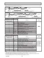
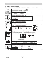
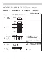
Setting by the DIP switch and jumper wire
Functions
Jumper wire
Model
settings
Capacity
settings
Pair number
setting with
IR wireless
remote
controller
For service board
Remarks
SW2
J41
J42
Unit type
setting
JP1
Indoor
controller
board type
setting
JP3
0
1
2
3–9
Wireless remote
controller setting
Control PCB setting
J41
J42
<Initial setting>
IR wireless remote controller: 0
Control PCB: (for both J41 and J42)
4 pair number settings are supported.
The pair number settings of the wireless remote
controller and indoor control PCB (J41/J42) are
given in the table on the left.
(' ' in the table indicates the jumper line is disco-
nnected.)
There is no jumper (JP1) because these models
have the cond./eva. temperature thermistor (TH5).
Jumper wire ( : Short : Open)
Without TH5
With TH5
Model
JP1
For product
Spare parts
Indoor controller board type
JP3
: with JP3
: without JP3
Service board
MODEL
PCA-A24KA7
1 2 3 4 5
1 2 3 4 5
1 2 3 4 5
ON
OFF
PCA-A30KA7
ON
OFF
PCA-A36KA7
PCA-A42KA7
ON
OFF
1 2 3 4 5
ON
OFF
MODEL
SETTING
PCA-A·KA7
ON
OFF
1 2 3 4 5
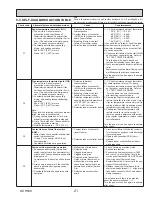
9-8. FUNCTIONS OF DIP SWITCH AND JUMPER WIRE
Each function is controlled by the DIP switch and the jumper wire on indoor controller board.
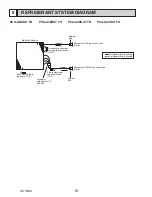
PCA-A24KA7.TH PCA-A30KA7.TH PCA-A36KA7.TH PCA-A42KA7.TH
The black square (
Ŷ
) indicates a switch position.
OCH638