

Test Run
6
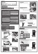
Measure an impedance between the power supply terminal block on the outdoor unit
and the ground with a 500V Megger and check that it is equal to or greater than 1.0 M
"
.
1
Turn on the main power to the unit.
2
Press the button twice continuously.
(Start this operation from the status of remote controller display turned off.)
A
TEST RUN
and current operation mode are displayed.
3
Press the ( ) button to activate COOL mode, then check whether
cool air is blown out from the unit.
4
Press the ( ) button to activate HEAT mode, then check whether
warm air is blown out from the unit. (only H/P model)
5
Press the button and check whether strong air is blown out from the unit.
6
Press the button and check whether the auto vane operates properly.
7
Press the ON/OFF button to stop the test run.
TEST RUN
MODE
MODE
FAN
VANE
NOTE : • Point the remote controller towards the indoor unit receiver
while following steps
2
to
7
.
• It is not possible to run in FAN, DRY or AUTO mode.
Function Selection
7
This setting is available only for Mr. Slim model. CITY MULTI model can be set by dip switch of indoor/outdoor
control circuit board. Refer to technical data of CITY MULTI model to set dip switch.
Each function can be set according to necessity using the remote controller.
The setting of function for each unit can only be done by the remote controller.
Select function available from the Table3. Function selection using wireless remote controller
is available only for refrigerant system with wireless function. Refrigerant address cannot
be specified by the wireless remote controller.
The article below describes how to set “LOSSNAY connectivity” into “supported
(indoor unit is not equipped with outdoor-air intake)” in Table 3 as an example.
1
Go to the function select mode
Press the button
F
twice continuously.
(Start this operation from the status of remote controller display turned off.)
CHECK
is lighted and “00” blinks.
Press the temp button
C
once to set “50”. Direct the wireless remote
controller toward the receiver of the indoor unit and press the button
A
.
2
Setting the unit number
Press the temp button
C
and
D
to set the unit number “00”. Direct
the wireless remote controller toward the receiver of the indoor unit and
press the button
B
.
3
Selecting a mode
Enter “03” to change the LOSSNAY connectivity setting using the
C
and
D
buttons. Direct the wireless remote controller toward the receiver
of the indoor unit and press the button
A
.
Current setting number: 1=1 beep (1 second)
2=2 beeps (1 second each)
3=3 beeps (1 second each)
W
If a mode number that can not be recognized by the unit is entered,
3 beeps (3 beeps of 0.4 seconds duration) will be heard.
Reenter the mode number selecting.
W
If the signal was not received by the sensor or an error occurred during
transmission, you will not hear a beep or a “double beep” may be heard.
Press the button again.
4
Selecting the setting number
Use the
C
and
D
buttons to change the LOSSNAY connectivity setting
to “02”. Direct the wireless remote controller toward the sensor of the indoor
unit and press the button
A
.
→ At this time, current setting number for selected mode number will be output
by the interrupted buzzer sounds and the blinks of operation indicator.
Output : setting number = 1 → beep beep (0.4 0.4 second) ×1
2 → beep beep (0.4 0.4 second) ×2
3 → beep beep (0.4 0.4 second) ×3
W
If a setting number that can not be recognized by the unit is entered, 3 beeps
(3 beeps of 0.4 seconds duration) will be heard (unit will beep only).
Reenter the setting number selecting.
W
If the signal was not received by the sensor or an error occurred during
transmission, you will not hear a beep or a “double beep” may be heard.
Press the button again.
W
If the number that can not be set is input, the former setting number will be set.
5
To select multiple functions continuously
Repeat steps
3
and
4
to change multiple function settings continuously.
6
Complete function selection
Direct the wireless remote controller toward the sensor of the indoor unit
and press the
button
E
.
CHECK
h
min
h
h
h
h
NOTE : Whenever changes are made to the function settings after construction or maintenance, be sure to record the
added functions with an “
○
”, in the “Check” column provided on the chart.
CHECK
CHECK
CHECK
CHECK
1
2
3
4
Other function selections
Now that you know how to change LOSSANY connectivity setting, there are several other settings that can be changed as well.
The following table lists the various settings that can be changed through the remote controller and the default settings.
Function
Settings
Not available
Available
Indoor unit operating average
Set by indoor unit’s remote controller
Remote controller’s internal sensor
Not supported
Supported (indoor unit is not equipped with outdoor-air intake)
Not supported (indoor unit is not equipped with outdoor-air intake)
100Hr
2500Hr
No filter sign indicator
Quiet
Standard
High ceiling
No vanes
Equipped with vanes (No.1 set)
Equipped with vanes (No.2 set)
○○
*1
○
○
○
○
PCA-RP·KA
○
○
○
○
–
○
PC-KAK
Power failure
automatic recovery
Indoor temperature
detecting
LOSSNAY connectivity
Filter sign
Fan speed (only for PCA)
Up/down vane setting
*1 It is possible to set it only while connecting wired remote control.
Things to remember when entering function selections:
The basic procedure for entering function selections is the same as described for switching between LOSSNAY connectivity.
However, there are some differences at step
2
for selecting the unit number, step
3
for selecting the mode number and
step
4
for selecting the setting number.
The following Tables 4 and 5 list the various function settings, mode numbers and setting numbers.
Table 4 details the function of the entire refrigerant system while Table 5 shows the function that can be set for the indoor unit.
Table 4. Itemized functions of the entire refrigerant system (select unit number 00)
Mode
Settings
Not available
Available (Approximately 4-minutes wait-period after power
is restored.)
Indoor unit operating average
Set by indoor unit’s remote controller
Remote controller’s internal sensor
Not supported
Supported (indoor unit is not equipped with outdoor-air intake)
Not supported (indoor unit is not equipped with outdoor-air intake)
01
02
03
Mode No.
Power failure
automatic recovery
Indoor temperature
detecting
LOSSNAY
connectivity
Setting No. Check
Remarks
1
2
1
2
3
1
2
3
Approximately 4-minutes wait-
period after power is restored.
Table 5. Itemized functions of the indoor unit (select unit numbers 01 to 04 or 07)
Mode
Settings
100Hr
2500Hr
No filter sign indicator
Quiet
standard
High ceiling
No vanes
Equipped with vanes (No.1 set)
Equipped with vanes (No.2 set)
07
08
11
Mode No.
Filter sign
Fan speed
(only for PCA)
Up/down vane
setting
Setting No. Check
Remarks
1
2
3
1
2
3
1
2
3
2
Setting the unit numbers
Set “00” as the unit number when setting function from Table 4.
When setting function from Table 5.
- When setting function for an indoor unit in an independent system, set the unit number to 01.
- When setting function for a simultaneous-Twin Triple quadruple indoor unit system, assign unit numbers from 01 to 04 to
each indoor unit.
- When setting the same functions for an entire simultaneous Twin Triple quadruple-indoor unit system, assign “07” as
the unit number.
3
Selecting the mode number
Select from Table 4 and Table 5.
4
Selecting the setting number.
Self-Check
8
1
Turn on the main power to the unit.
2
Press the button twice continuously.
(Start this operation from the status of remote controller display turned off.)
A
CHECK
begins to light.
B
“00” begins to blink.
3
While pointing the remote controller toward the unit’s receiver, press
the button. The check code will be indicated by the number of
times that the buzzer sounds from the receiver section and the number
of blinks of the operation lamp.
4
Press the ON/OFF button to stop the self-check.
CHECK
h
[Output pattern A] Errors detected by indoor unit
[Output pattern B] Errors detected by unit other than indoor unit (outdoor unit, etc.)
E9
*1
If the beeper does not sound again after the initial
2 beeps to confirm the self-check start signal was received and
the OPERATION INDICATOR lamp does not come on,
there are no error records.
*2
If the beeper sounds 3 times continuously “beep, beep, beep (0.4 + 0.4 + 0.4 sec.)” after the initial 2 beeps to confirm
the self-check start signal was received, the specified refrigerant address is incorrect.
OPERATION
INDICA
TOR
lamp blink
pattern
Beep
Beep Beep Beep
Beep
Beep
Beep
Off
Approx. 2.5 sec.
On
Approx. 3 sec.
On
0.5 sec.
On
0.5 sec.
On
0.5 sec.
On
0.5 sec.
Off
Approx. 2.5 sec.
On
Approx. 3 sec.
On
0.5 sec.
On
0.5 sec.
· · ·
Repeated
Number of blinks/beeps in pattern indicates the check
code in the following table (i.e., n=5 for “U2”)
Number of blinks/beeps in pattern indicates
the check code in the following table
n
th
1
st
2
nd
3
rd
1
st
2
nd
Self-check
starts
(Start signal
received)
Beeper sounds
[Output pattern B]
OPERATION
INDICA
TOR
lamp blink
pattern
Beep
Beep Beep Beep
Beep
Beep Beep
Off
Approx. 2.5 sec.
On
0.5 sec.
On
0.5 sec.
On
0.5 sec.
On
0.5 sec.
Off
Approx. 2.5 sec.
On
0.5 sec.
On
0.5 sec.
· · ·
Repeated
Number of blinks/beeps in pattern indicates the check
code in the following table (i.e., n=5 for “P5”)
Number of blinks/beeps in pattern indicates
the check code in the following table
n
th
1
st
2
nd
3
rd
1
st
2
nd
Self-check
starts
(Start signal
received)
Beeper sounds
●
Refer to the following tables for details on the check codes.
[Output pattern A]
Beeper sounds/OPERATION
INDICATOR lamp blinks
Check code
Symptom
Remarks
(Number of times)
Wireless remote controller Wired remote
controller
Beeper sounds/OPERATION
INDICATOR lamp blinks
Check code
(Number of times)
Wireless remote controller
1
2
3
4
5
6
7
8
9
10
11
12
No sound
No sound
No sound
P1
Intake sensor error
P2, P9
Pipe (Liquid or 2-phase pipe) sensor error
E6,E7
Indoor/outdoor unit communication error
P4
Drain sensor error/Float switch connector open
P5
Drain pump error
P6
Freezing/Overheating safeguard operation
EE
Communication error between indoor and outdoor units
P8
Pipe temperature error
E4
Remote controller signal receiving error
–
–
–
–
Symptom
Remarks
1
2
3
4
5
6
7
8
9
10
11
12
13
14
Indoor/outdoor unit communication error
(Transmitting error) (Outdoor unit)
Open/short of outdoor unit thermistors
Compressor overcurrent interruption (When compressor locked)
Abnormal high discharging temperature/
insufficient refrigerant
Abnormal high pressure (63H worked)/Overheating
protection operation
Abnormal temperature of heat sink
– (Outdoor unit error)
Compressor overcurrent interruption/Abnormal of power module
Abnormality of super heat due to low discharge temperature
Abnormality such as overvoltage or voltage shortage and
abnormal synchronous signal to main circuit/Current sensor error
U2
U5
UP
U3,U4
UF
U1,Ud
U8
U6
U7
U9,UH
Others
–
–
–
–
Other errors (Refer to the technical manual for the outdoor unit.)
For details, check
the LED display
of the outdoor
controller board.
Fb
E0, E3
E1, E2
– – – –
Indoor unit control system error (memory error, etc.)
Compressor overcurrent interruption
• On wireless remote controller
The continuous buzzer sounds from receiving section of indoor unit.
Blink of operation lamp
• On wired remote controller
Check code display in the LCD.
Wired remote
controller
ON/OFF
TEMP
FAN
VANE
TEST RUN
AUTO STOP
AUTO START
h
min
LOUVER
MODE
CHECK
RESET
SET
CLOCK
NOT AVAILABLE
SWING
TEST
RUN
3
4
6
5
7
2
A
ON/OFF
TEMP
FAN
VANE
TEST RUN
AUTO STOP
AUTO START
h
min
LOUVER
MODE
CHECK
RESET
SET
CLOCK
CHECK
F
E
B
A
CD
ON/OFF
TEMP
FAN
VANE
TEST RUN
AUTO STOP
AUTO START
h
min
LOUVER
MODE
CHECK
RESET
SET
CLOCK
CHECK
2
4
3
A
B
Table 3.
Remote controller transmission error
Remote controller control board error
No corresponding
RG79V995H03
1
Output pattern (Mr.Slim model / CITY MULTI model)
2
Check code (Mr.Slim model)
3
Check code (CITY MULTI model)
Beeper sounds/OPERATION
INDICATOR lamp blinks
Check code
Remarks
(Number of times)
Wireless remote controller
Wired remote
controller
1
2
3
4
5
6
7
8
9
1000 ~ 1999
2000 ~ 2999
3000 ~ 3999
4000 ~ 4999
5000 ~ 5999
6000 ~ 6999
7000 ~ 7999
0000 ~ 0999
8000 over
[Output pattern A] Errors detected by indoor unit or LOSSNAY unit
[Output pattern B] Errors detected by unit other than indoor unit (outdoor unit, etc.)
*2
If the beeper does not sound again after the initial
2 beeps to confirm the self-check start signal was received and
the OPERATION INDICATOR lamp does not come on,
there are no error records.
*3
If the beeper sounds 3 times continuously “beep, beep, beep (0.4 + 0.4 + 0.4 sec.)” after the initial 2 beeps to confirm
the self-check start signal was received, the specified address is incorrect.
• On wireless remote controller
The continuous buzzer sounds from receiving section of indoor unit.
Blink of operation lamp
• On wired remote controller
Check code display in the LCD.
*1 Refer to service handbook of outdoor unit for the detail.
HEAD OFFICE:
TOKYO BUILDING, 2-7-3, MARUNOUCHI, CHIYODA-KU,
T
OKYO 100-8310, JA
PAN


