

10
A1 A2
9
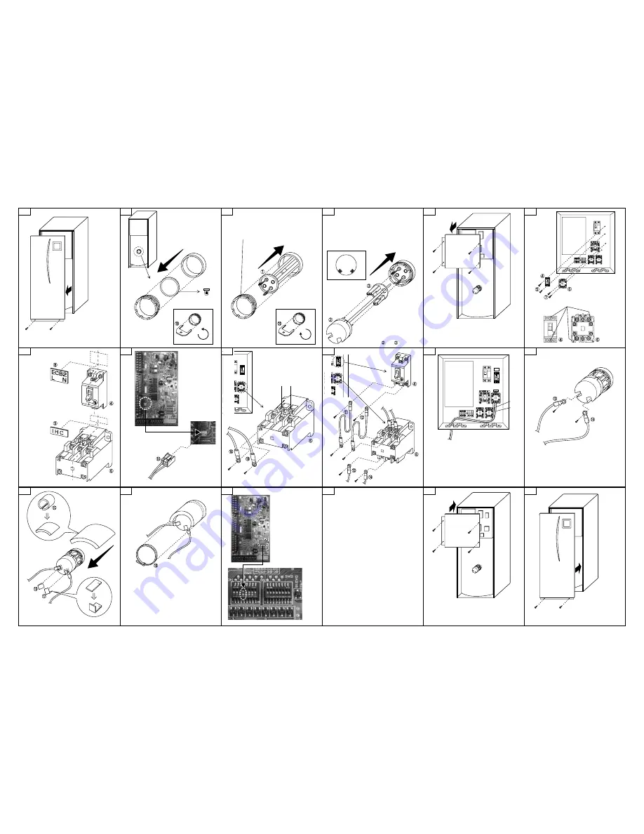
Carefully remove front panel
by disconnecting the control
cable from beneath the unit’s
main control box.
1
The blanking plate and gasket
can be removed using a narrow
flat bladed screwdriver.
Dispose
Check before starting installation
that no water is in the tank.
2
Diagonally locate the thermostat pockets on upper
right and bottom left with termini on the upper left
and bottom right sides as shown.
Secure tightly with the nut to prevent water leakage.
(Recommended torque = 10 N•m)
3
Reinstate plastic tab cover over
the connectors then insert the
thermostat rod into the upper
right hand pocket.
The terminals on the white
plastic head should be positioned
at the bottom as shown.
4
Assemble and securely.
5
Screw positions
6
Place the terminal
blocks so that the
orientations of the
labels are correct.
7
Align the centre lines
and
as shown.
Align the centre
lines
and
as shown.
Connector CNIH
8
11
Do not insert the lead wires
and
into the
opening that the main controller wires or the
wireless receiver wires use.
12
13
Run the lead wire through
the slit on the water-proof
cover provided and seal
each terminal screw.
14
Place the band on the joint surface of the
DHW tank.
Secure the water-proof cover around the
cylinder boss using the band provided.
15
Dip Switch
1-4 OFF
→
ON
(without immersion heater
→
with immersion heater)
17
18
Carefully reinstate control cable
connection before reinstating
and securing the front panel.
16
For details about wiring to power supply and
circuit breaker, refer to the installation
manual for the cylinder unit.
Fill tank with water and ensure that no water
leaks around the periphery of the immersion
heater.
BH79D212H02