background image

2 -  2

2. HOW TO USE THE SOFTWARE

2.1.3 Operation procedures within the window

Within the operation window, enter data and/or press the button.

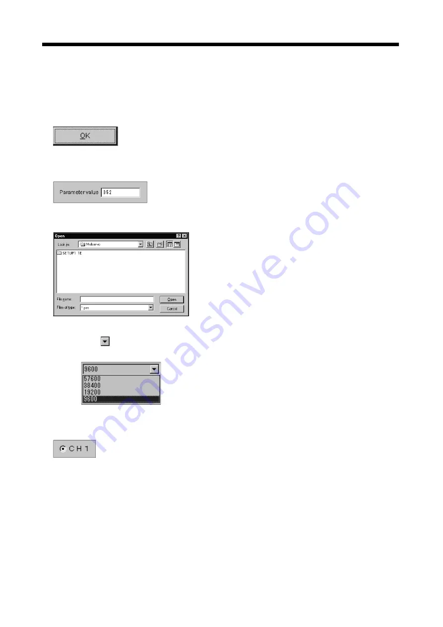
(1) Pressing a button

Click the button in the window.

(2) Entering data

Click the setting area to move the focus there, and enter data from the keyboard.

(3) Selecting data

Click the data to be selected.

6

(4) Selecting the combo box data, etc.

1) Click   on the right of the setting portion to open the combo box.
2) Make selection by clicking the data or like to be chosen.

(5) Pressing the option button

Click the item or button.

Summary of Contents for MRZJW3- SETUP161E

Page 1: ...hi general purpose AC servo MELSERVO Servo Configuration Software To optimize the use of the Servo Configuration Software please read over this Instal lation Guide and the corresponding AC servo Installation Guide before using the soft ware After reading the Installation Guide always place this Installation Guide in a safe place F ...

Page 2: ... they are important to personnel safety What must not be done and what must be done are indicated by the following diagrammatic symbols Indicates what must not be done For example No Fire is indicated by Indicates what must be done For example grounding is indicated by In this Installation Guide instructions at a lower level than the above instructions for other functions and so on are classified ...

Page 3: ...A 2 MEMO ...

Page 4: ...tallation procedure 1 10 2 HOW TO USE THE SOFTWARE 2 1 to 2 8 2 1 Operation 2 1 2 1 1 Start up 2 1 2 1 2 Command selection procedures 2 1 2 1 3 Operation procedures within the window 2 2 2 2 Commands and display windows 2 3 2 3 Precautions for test mode 2 6 2 4 Simple language for program operation 2 7 2 4 1 Language 2 7 2 4 2 Program example 2 8 2 4 3 Instruction 2 8 3 TROUBLESHOOTING 3 1 to 3 2 ...

Page 5: ...2 MEMO ...

Page 6: ...s selection System Automatic demo Display all High speed monitor Multi axis listing Multi station listing Monitor Trend graph Display History Alarm Amplifier data I O display Function device display No motor rotation Total power on time Software number display Motor data display Tuning data Absolute encoder data Automatic voltage control Axis name setting Unit composition listing Fully closed diag...

Page 7: ...play Function device display No motor rotation Total power on time Software number display Motor data display Tuning data Absolute encoder data Automatic voltage control Axis name setting Unit composition listing Fully closed diagnostics Diagnostic Linear diagnostics Parameter list Tuning Change list Detailed information IFU parameter DRU parameter Parameters Device setting Jog Positioning Operati...

Page 8: ...XP Professional Windows XP Home Edition Free hard disk space 60MB or more Serial port used OS Windows 95 Windows 98 Windows 98 Second Edition Windows Me Windows NT Workstation 4 0 Windows 2000 Professional Windows XP Professional Windows XP Home Edition English version Display One whose resolution is 800 600 or more and that can provide a high color 16 bit display Connectable with the above person...

Page 9: ...tion Connector 10120 6000EL Shell kit 10320 3210 000 3M Connector DE 9SF N Case DE C1 J6 S6 Japan Aviation Electronics MR CPCATCBL3M 3 9 84 For IBM series D SUB 9 pins For fabrication refer to the connection diagram in this section When fabricating the cable read and follow the instructions below 1 Always use a multi core cable with a shield and connect the shield to FG securely 2 Wiring distance ...

Page 10: ...pe of your personal computer 1 2 3 Configuration diagrams 1 MR J2S A MR J2S B MR J2S CP MR J2S CL MR J2S B PY096 MR J2S B S096 MR J2S B S009U MR J2S A PY091 MR J2S A S091 MR J2S CP S084 MR J2S A S040U MR J2S A S240U CN3 CN2 Personal computer Communication cable Servo amplifier To RS 232C connector Servo motor 2 MR J2M P8A MR J2M P8B CN3 CN2 To RS 232C connector Communication cable DRU First slot D...

Page 11: ...ld down the left button of the mouse and move the mouse 6 Focus Highlights characters button or the like when the menu or button is ready to accept an input from the keyboard 7 Text box Box used to enter characters 8 List box Box used to select one of several items 9 Combo box Box used to select one of several items 10 Check box Box used to select one or more of several items When a choice is made...

Page 12: ...ottom at top right corner of the window Click 2 Moving the focus from one window to another Click the button of the task bar corresponding to the window to be used Click 3 Moving the window Point to the title bar drag the window to the required position and release the button Drag ...

Page 13: ...Click the object to be operated such as a text box When the object to be operated is a button clicking it will start its processing Click Click Short cut keys Any of the following short cut keys may be used to perform operation from the keyboard Intended operation Keyboard Show help F1 End program Alt F4 Show start menu Ctrl Esc Change window Alt Tab Change object Tab ...

Page 14: ...CTION 1 5 Screen definitions b e d a c a Title bar b Menu title c Menu bar Shows the menu title d Menu Command menu in tier 1 e System setting display area Shows the servo amplifier and baud rate which have been set ...

Page 15: ...s program always close all Windows programs 1 Insert CD ROM in Drive D CD drive Then click the Start button of the task bar to open the start menu specify the file name and click Run When the following window has appeared type D SETUP161E DISK SETUP EXE and click the OK button D SETUP161E DISK SETUP EXE 2 After the above window the following window appears Click Next button ...

Page 16: ... User Information screen appears Type your full name and company name and click Next button 4 The Choose Destination Location screen appears When you specify the destination folder and click Next button installation starts 161 ...

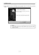
Page 17: ...ODUCTION 5 When installation ends any of the following screens appears Click the Finish button to exit from Setup POINT In the corresponding window to stop installation click the Cancel button or press the Escape ...

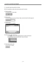
Page 18: ...ton of the task bar to open the menu 2 Point to submenu MELSERVO SETUP_Software from Programs 3 Click SETUP161E 2 1 2 Command selection procedures 1 Clicking method 1 Click the menu title on the menu bar to open the menu 2 Point to and click the command to be selected 2 Dragging method Point to the menu title on the menu bar hold down the left button and drag the mouse to the command to be selecte...

Page 19: ...n in the window 2 Entering data Click the setting area to move the focus there and enter data from the keyboard 3 Selecting data Click the data to be selected 6 4 Selecting the combo box data etc 1 Click on the right of the setting portion to open the combo box 2 Make selection by clicking the data or like to be chosen 5 Pressing the option button Click the item or button ...

Page 20: ...ory Amplifier Data Alarm Display Alarm History Amplifier Data Demo Operation Mode Program Operation Edit Amplifier Data Amplifier Data Display Monitor detailed information Alarm reset Alarm history clear Command Display window To next page Version information Axis Selection Axis Selection Version information High Speed Monitor High Speed Monitor Amplifier Monitor Parameter Selection Trend Graph Gr...

Page 21: ...ber display Software number display Absolute Encoder Data Auto tuning Manual mode 2 Manual mode 1 Axis name setting Axis name setting Unit composition listing Unit composition listing Automatic Voltage Control Tuning Data Motor Data Display Total Power on Time No Motor Rotation Function device display Motor output disabled Parameter change list Parameter detailed information IFU Parameter IFU Para...

Page 22: ...otor Forced Output Demo Mode Machine analyzer Gain search Machine simulation Point data Advanced function Machine analyzer Gain search Machine simulation Menu Command Display window Single step Feed Single step Feed Help Help Point table Continued from preceding page Program test Program test Program display Program data Program Data Indirect Addressing Program Data Program Edit Indirect Addressin...

Page 23: ...put signal SON is automatically switched on in the servo amplifier to start operation independently of the ON OFF status of SON Also any external command pulse or input signal except emergency stop is not accepted until the test mode window is closed to terminate the command SON is automatically switched on by the following operation Test mode Mouse Jog Click the Forward or Reverse button The serv...

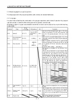
Page 24: ...ate SPN and acceleration deceleration time STC No symbol CCW rotation CW rotation This command is available for the MR J2S A MR J2M P8A Used to hold the next operation until the preset digital input signal DI of the servo amplifier switches on By setting 99 the next operation will be performed unconditionally Set the input signal as listed below For the MR J2S A any signal not allocated by signal ...

Page 25: ...eration deceleration time to 1200ms MOV 12000 Executes movement by 12000 pulses in the CCW direction TIM 10 Hold the next operation for 10s SPN 2000 Sets the command speed to 2000r min MOV 100000 Executes movement by 100000 pulses in the CW direction STOP In this example the acceleration deceleration time in Operations 1 and 2 are the same In this case the acceleration deceleration time in Operati...

Page 26: ...onal computer 002 Checksum error occurred in the data sent from the personal computer 003 Character not given in the specifications was sent to the servo amplifier 004 Command not given in the specifications was sent to the servo amplifier 005 Data number not given in the specifications was sent to the servo amplifier Data outside the permissible range was sent to the servo amplifier None Checksum...

Page 27: ...3 2 3 TROUBLESHOOTING MEMO ...

Page 28: ...nspection at Delivery Section 1 2 1 Table reexamination Section 1 2 2 1 Addition of MR J2S CL MR J2S B PY098 S096 S009U Section 1 2 2 2 Text deletion Section 1 2 3 1 MR J2S CL MR J2S B PY098 S096 S009U Section 1 5 Screen change Section 1 6 POINT deletion text modification reexamination Section 2 1 2 Screen change Section 2 2 Addition of full closed diagnosis and linear diagnosis to the diagnosis c...

Page 29: ... OFFICE MITSUBISHI DENKI BLDG MARUNOUCHI TOKYO 100 8310 IB NA 0300017 F 0402 MEE Printed in Japan Specifications subject to change without notice This Installation Guide uses recycled paper MODEL MODEL CODE ...

Reviews: