18
JEP0-IL9554
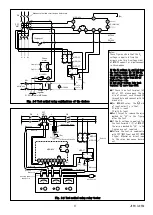
Terminal layout
9
9
9
9
9
9
14
P1
M
a11
a12
Y1
Z1
×
P2
N
a21
a22
Y2
Z2
E
MDG-A3V-R/RD
Do not connect to the "
×
" terminals, or the relay may not operate properly.
Fig. 2-7 Terminal layout
Drawing out and housing operation of subunit (Unit-drawer type)
For unit-drawer type (RD type), it is possible to draw
out the subunit from the case without removing external
wiring, which makes easier to carry out inspection and
testing.
When drawing out and housing, be careful not to touch the
electrical circuit (e.g. substrate, capacitor, and
transformer) and be sure to hold the drawer handle or the
frame part when transporting. (Touching the electrical
circuit may cause electric shock or damage to the
circuit.)
Before the subunit is to be drawn out, ensure that the
following items are checked in order not to carry out the
work in hot-line condition.
・
Lock of the tripping circuit
・
Turning off the main circuit
・
Disconnect CT/VT circuit
・
Turning off the auxiliary power supply
The CT circuit is equipped with an automatic short circuit
piece so that the CT secondary circuit won't be opened
even if the relay subunit is drawn out without
disconnecting the CT circuit.
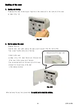
Fig. 2-8 Structures of unit-drawer type (RD type)
Connector of case
Drawer handle
(Back side)
Connector of subunit
(Back side)
Subunit
Cover (Transparent)
Drawer fixing
screw


