Installation
Handling the robot controller
FR series
3 - 25
3.4.2 Installing
the CR800 controller
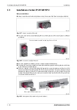
The illustration below shows the installed CR800 controller. Please observe these important instruc-
tions:
●
The controller and drive unit can be installed vertically or horizontally.
●
The lateral clearances must not be less than shown in Fig. 3-16.
●
Take steps to ensure that the maximum permitted ambient temperature of 40 °C is never exceed-
ed when installing the units in switch-gear cabinets.
R002756E
Fig. 3-16:
Installation of the CR800 controller
145 mm
145 mm
170 mm
150 mm
150 mm
150 mm
50 mm
20 mm
Air intake
Air intake
Horizontal installation
Vertical installation
Summary of Contents for MELFA RH-FRH-D
Page 2: ......
Page 4: ......
Page 6: ......
Page 16: ...Contents X ...
Page 22: ...Environmental conditions for operation Introduction 1 6 ...
Page 70: ...Grounding the robot system Installation 3 32 ...
Page 90: ...Teaching Box connection Connection 4 20 ...
Page 96: ...Switch on the robot system Startup 5 6 ...
Page 128: ...Dimensions Appendix A 18 ...
Page 130: ...A 20 Index Appendix ...
Page 131: ......
Page 132: ......
Page 133: ......
Page 134: ......
Page 135: ......
Page 136: ......
Page 137: ......
Page 138: ......
Page 139: ......
Page 140: ......
Page 141: ......
Page 142: ......
Page 143: ......
Page 144: ......
Page 145: ......
Page 146: ......
Page 147: ......
Page 148: ......
Page 149: ......
Page 150: ......
Page 151: ......
Page 152: ......
Page 153: ......
Page 154: ......
Page 155: ......
Page 156: ......
Page 157: ......
Page 158: ......
Page 159: ......
Page 160: ......
Page 161: ......
Page 162: ......
Page 163: ......
Page 164: ......
Page 165: ......

