background image

8.1.2 

MFM  Encoding

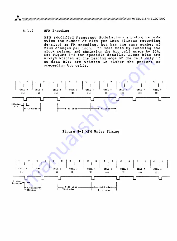
M F M   (Modified  Frequency  Modulation)  encoding  records


twice  the  number  of  bits  per  inch  (linear  recording


density)  as  FM  encoding,  but  has  the  same  number  of


flux  changes  per  inch. 

It  does  this  by  removing  the


clock  pulses,  and  shrinking  the  bit  cell  space  by  50%.


See  Figure  8-2  for  specific  details.  Clock  bits  are


always  written  at  the  leading  edge  of  the  cell  only  if


no  data  bits  are  written  in  either  the  present  or


preceeding  bit  cells.

Summary of Contents for M4853

Page 1: ...5 25 INCH FLEXIBLE DISK DRIVE MODEL M4853 MAINTENANCE MANUAL STANDARD MITSUBISH ELECTRIC ...

Page 2: ...2 4 1 Environment 2 4 2 Diskette Handling 3 5 Regular Maintenance 4 5 1 Caution 4 5 2 Head Cleaning 5 5 3 Check and Adjustment 6 5 3 1 Diskette rotation cycle adjustment 6 5 3 2 TK 00 sensorposition adjustment 8 5 3 3 Index sensor position check 10 5 3 4 Head alignment adjustment 11 5 3 5 Head Azimuth check 13 ...

Page 3: ...adjustment of M4853 Flexible disk unit 2 References schematics and manuals M4852 53 Specifications SJ2 G3375C PCA NAMFB schematic diagram for maintenance TJ2 G30144A Illustrated parts list TJ2 G4865A Packing manual 10 set TJ2 4869A 3 Names of Unit Parts FIGURE 1 ...

Page 4: ...st less than 3 0G 5 100 HZ Be extra careful of dust antering unit because it may cause damage to head or diskette media 4 2 Diskette Handling Be extra careful of the following 1 Keep diskette media away from any appliance which may generate magnetic field ex Radio TV Motor Dynamo and other electrical appliances 2 Do not bring any ferro magnetic materials near the diskette 3 Do not bend media under...

Page 5: ...FIGURE 2 ...

Page 6: ...erform maintenance once a year 5 1 Caution 1 During maintenance be careful of dust entering unit and damaging head 2 Make sure power switch is off first when starting maintenance 3 When put off on Printed circuit Board P C B Assy make sure power switch is off to protect semiconductors and ICs 4 Do not touch Disk media surface or head directly and do not bring any ferro magnetic materials near it 5...

Page 7: ... high humidity high and low extreme temparatures Low temperature such as 5 to 10 C 41 to 50 F under high humidity is most severe for diskettes iii Higher frequency for brand new drives would be recommended for about once a week Better matchning between head and medium would be produced by a long time use as experienced 2 When frequent errors are detected Wet or dry type may be used 3 When scratch ...

Page 8: ...er switch 2 2 Load diskette then turn on motor with drive select 2 3 Make sure HLMG ON 2 4 Seek to TKOO 2 5 Connect universal counter to INDEX interface signal TPD14 and measure rotational cycle rate 2 6 Adjust counter reading until it comes within specifications using SPM VR see Figure 4 2 7 After this adjustment Lock VR with white paint 3 Test specification 3 1 Check 1 6 196 8 203 2 ms 3 2 Adjus...

Page 9: ...INDEX TPD14 FIGURE 4 ...

Page 10: ...tte 2 2 Turn on motor and select drive 2 3 Repeat seek between TKOO and 02 see Figure 5 2 4 Observe waveform TKOO at TPB1 using oscilloscope trigger CHI step DC TPD15 signal CH2 TKOO DC TPE1 2 5 Loosen screw and adjust TimeT until it comes to within 3 4ms by moving TKOO in the direction of the arrow see Figure 3 Note 3 1 Set step rate at 3ms using Disk Tester 3 2 Make sure there are 2 pulses on st...

Page 11: ...FIGURE 5 ...

Page 12: ...to drive set power off 2 2 Load diskette 2 3 Turn on power switch 2 4 Turn on and select drive 2 5 Read timing of each waveform at TPB9 TPB10 under read mode TK02 using oscilloscope see figure Trigger EXT INDEX DC TPD14 Signal CHI TPB9 AC CH2 TPB10 AC INV Specification Adjust 200 100 ys at TK02 Side 0 2001200 ys at TK02 Side 1 Check 200 200 ys at TK02 Side 0 2001300 ys at TK02 Side 1 ...

Page 13: ...ette close clamp door slowly 2 4 Seek TKOO to TK32 then read amplitude of each wave form positioning waveform read mode see Figure 7 at TPB9 TPB10 under Tigger EXT INDEX DC TPD14 Signal CHI CH2 TPB9 TPB10 AC AC INV Add Specification when A B A B B A A B CHECK 0 57 0 57 ADJUST 0 6 0 6 21 6 In case seek direction is TKOO TK32 or TK79 TK32 loosen both set screws then adjust STM until signal comes wit...

Page 14: ...FIGURE 7 ...

Page 15: ...re 2 1 Connect CE Tester to Drive then turn on power switch 2 2 Turn on motor 2 3 Select drive and load CE diskette 2 4 Seek to TK68 2 5 Read azimuth waveform using oscilloscope Trigger EXT INDEX DC TPD14 Signal CHI CH2 TPB9 TPB10 AC AC INV Add 2 6 Acceptable following when range adjusted wave form within FIGURE 8 ...

Page 16: ...he head s azimuth is not adjustable It is suggested that the drive be sent to an authorized repair center or a new head assembly be installed In the latter case all previous adjust ments should be made again ...

Page 17: ...TJ2 G302 31A 5 25 INCH FLEXIBLE DISK DRIVE M4853 PCB NAMFF PARTS LIST 10 31 83 MITSUBISHI ELECTRIC ...

Page 18: ...n P2 172296 1 Connector Accery 1 AMP Japan P3 65625 114 6 Connector 1 JAE Japan PM2 00 8261 1432 10 854 Connector 2 Elco Inti J1 J2 J3 J4 J5 J6 J7 J8 J9 J10 J12 J13 00 8261 0282 00 878 Connector 12 Elco Inti P5 IL SP S 3EN2 N 1 Connector 1 JAE Japan P4 PS 12PA D4LTI A1 Connector 1 JAE Japan KEISAKI J21101 Index Sensor Assy 1 Kodenshi Kogyo Japan KEISAKI J2110 0 Write Protect Sensor Assy 1 Kodenshi...

Page 19: ...5 6 28 RPE122 127C223K50 Capacitor Cer 0 022yF1 50V 10 3 I I C7 8 70 RPE122 127CH102J50 Capacitor Cer 1000pF 50V 5 3 I t CIO RPE122 127C103K50 Capacitor Cer 0 OlyF 50V 10 1 I I C3 RPE122 127CH101J50 Capacitor Cer lOOpF 50V 5 1 I I C U RPE122 127CH331J50 Capacitor Cer 330pF 50V 5 1 I I Cl2 RPE122 127CH151J50 Capacitor Cer 150pF 50V 5 1 I t C64 65 66 67 RPE122 127C104K50 Capacitor Cer 0 lyF 50V 10 4...

Page 20: ...S04P IC Digital 2 IC E5 J2 MR4LS08P IC Digital 2 IC Gl M74LS86P IC Digital 1 IC H2 M74LS10P IC Digital 1 IC Kl M74LS123P IC Digital 1 IC B5 C6 M53238P IC Digital 2 IC A3 1 A3 2 M54542L IC Linear 2 IC D6 NE555P IC Linear 1 Texas Inst IC L5 AS 1412 02 IC Hybrid 1 IC L6 AS 1413 IC Linear 1 IC H5 MC 347OP IC Linear 1 Motorola IC El MPA2003C IC Linear 1 NEC Japan IC H6 SN75472P IC Linear 1 Texas Inst ...

Page 21: ...sistor 6 8kft W 1 2 I I R8 9 NL J2201F Resistor 2 2kft3sW 1 2 I I R28 NL J2702F Resistor 27kft W 1 1 I I Rll 12 NL J3300F Resistor 330ft 5 W 1 2 I t R13 14 36 38 41 49 50 61 62 63 64 80 82 83 85 86 87 93 NLJsJlOOlF Resistor lkft 3 s W 1 15 I I R1 10 NIAJ3301F Resistor 3 3kft3 W 1 2 I I R19 21 NL J1002F Resistor lOkft W 1 2 I I R22 NL J4 7R0F Resistor 47 f t 1 1 I I R25 31 39 53 NL J1500F Resistor ...

Page 22: ...1F Resistor 1 5k W 1 3 ii R9 2 NLVJ1502F Resistor 15k 7 1 1 it R89 RN W56 0J Resistor 56 W 5 1 Hokuriku Elec R2 RNC1W271J Resistor 270 IW 5 1 Japan RM1 M16A 151J Resistor Module 1 Iwaki Musen R2 3 PSR1 5B121J Resistor Module 1 Japan R20 29 3321p l 503 Resistor Variable 50kfi 2 Murata Works Japan LI 2 TP0410 681J Inductor 680pH 5 2 TDK Japan L 4 TP0206 101K Inductor lOOyH 10 1 1 TRI 2 2SA952 Transi...

Page 23: ...303 Diode Zener 3V 1 Dl 0 RD6 8FB Diode Zener 6 8V 1 NEC Japan D5 RD5 1FB Diode Zener 5 1V 1 NEC Japan Dl 2 RD3 0EB2 Diode Zener 3V 1 NEC Japan D2 3 4 6 11 IS 954 Diode National Component Inc Dl 3 NDP127 Diode 1 National Component Inc D3 4 DC447536 G01 Diode Pair 2 ...

Page 24: ...ATIONS 6 1 Installation Direction Install the M4853 disk drive in the directions shown in Pig 6 1 The slant mount should be within 10 degrees Fig 6 1 Disk Drive Installation Directions 6 2 Dinunensions of M4853 See Fig 6 2 ...

Page 25: ......

Page 26: ...n only be one drive 0 etc in a system 7 2 MX If only one FDD is in a system this option may be used to constantly select the drive It causes the drive to ignore the status of the DS lines This jumper must be removed in multi drive systems 7 3 HS This plug is installed to cause the heads to load when the drive is selected by DSO through DS3 This occurs after the drive is ready see section 7 3 Do no...

Page 27: ...FIGURE 7 1 H and R Jumper Options ...

Page 28: ...puted from the drive to the head load circuit ready qualification input This is done when both the H and R jumpers should be installed on the same option H 2 R 2 or H 3 R 3 which is physically impossible In the case of H 3 R 3 the R jumper should be installed in the R 3 position and the H jumper should be installed in the H l position 7 9 H 2 Installing the H jumper in position 2 routes the curren...

Page 29: ... option is not used at this time 01 Cutting this PCB trace disables the in use input to the drive Pl 4 This means that the only time the front panel LED will be lit will be when the drive is selected The MX option cannot be used in conjunction with this modification the in use LED will never be illuminated if it is Write Protect Inversion The option pads between IC s Ml and LI are used to invert t...

Page 30: ...Nota See Section 7 17 for description of this unmarked option ...

Page 31: ...he disk drive just records and detects flux reversals on the disk 8 1 As stated before there are three main methods of encoding bits on a floppy disk All have some advantages and disadvantages but the generally accepted standard is MFM also called Double Density 8 1 1 FM Frequency Modulation encoding is shown in Figure 8 1 It is the simplest form of encoding and may be decoded by used of inexpensi...

Page 32: ...sity as FM encoding but has the same number of flux changes per inch It does this by removing the clock pulses and shrinking the bit cell space by 50 See Figure 8 2 for specific details Clock bits are always written at the leading edge of the cell only if no data bits are written in either the present or preceeding bit cells ...

Page 33: ...between data pulses It is not a standard encoding technique and should probably be avoided for that reason See Figure 8 3 for a description of MMFM The data bits are written in the middle of the data cells but a clock pulse is encoded only if no clock or data pulses were written in the previous bit cell and no data bit is to be written in the present one Figure 8 6 MMFM Read Timing ...

Page 34: ...e as attached sheets including formatting and data re write modes The drives are sufficient for the following considerations for all 80 tracks 1 The leading edge of a data block should be preceded by the erased area when re write 2 The trailing edge of a data block should be covered by the erased area when re write 3 The erased area should not overlap with Sector Identifiers 4 Read Write gap shoul...

Page 35: ......

Page 36: ......

Page 37: ......

Page 38: ......

Page 39: ......

Page 40: ...soft errors o Dust is caught between the read write head and diskette causing temporary fault in head contact Such dust is generally removed by the self cleaning wiper of the jacket and the data is recovered by the next re read operation If read write is continued for a long time in a very dusty environment however hard errors can result from a damaged diskette surface o Random electrical noise ra...

Page 41: ... or until the data is recovered o Step 2 If the data cannot be recovered by Step 1 move the head to another track the opposite direction of the previous track position before the designated track and then return the head to the original position o Step 3 Repeat an operation similar to Step 1 O Step 4 If the data cannot be recovered assume the error is a hard error o ...

Page 42: ...9 0 RESHIPMENT PRECAUTIONS When reshipping the drive make sure the protection sheet for transportation is in place in the drive and the door is secured open ...

Page 43: ......

Page 44: ......

Page 45: ......

Page 46: ......

Page 47: ......

Page 48: ...TJ2 630232A H 5 25 INCH FLEXIBLE DISK DRIVE M4853 ILLUSTRATED PARTS LIST ...

Page 49: ...IVE FLEXIBLE DISK DRIVE MECHANISM ASSY PCA NAMFF Carnage Assy C a r t r i g eGuide Assy Frone P a n e iAssy E j e c t o rAssy C o l l e tAssy i g No P a g e o 1 3 5 3 7 4 8 5 1 0 6 11 7 1 2 8 1 3 4 FLEXIBLE DISK DRIVE WIRING DIAGRAM 9 1 4 ...

Page 50: ...M4853 F l e x i b l eD i s k D r i v e ...

Page 51: ......

Page 52: ...F i g u r e 1 F l e x i b l e D i s k D r i v e ...

Page 53: ......

Page 54: ...F i g u r e 2 Medianism Assy ...

Page 55: ......

Page 56: ......

Page 57: ......

Page 58: ......

Page 59: ......

Page 60: ......

Page 61: ......

Page 62: ......

Page 63: ...5 25 INCH FLEXIBLE DISK DRIVE Differences Between M4853 and M4853 1 ...

Page 64: ...ion with HOLD READY No other optional choice 2 Choosing motor operation condi tions During MM short the motor will start with the ON signal During MS short the motor will start with the Drive Select signal When both are in short it will start with logical add And when both are open the motor will not start Combinations of open and short circuits between MM and MS allow the choice of one of the 4 f...

Page 65: ...nd 2S is open With HOLD READY DC is open and 2S is shorted In the PCB pattern DI is cut off and short plug J3 is shorted Short plug IU is open 3 Interchangeability of parts Parts M4853 and M4853 1 are not interchange able 4 Others The electrical interface power supply interface with the controller is the same for M4853 and M4853 1 The power supply connector and electrical interface connector are i...

Page 66: ......

Page 67: ...ont panel has been strengthened Metal frame on in side of front panel 3 Depth has been decreased Circuit boards pro trude 8mm beyond back of frame Back edge of frame and printed circuit board are even Structural parts 1 Interchange ability No interchangeability of parts between the M4853 and the M4853 1 Others 1 Mounting inter changeability The mounting interchangeability is the same the M4853 and...

Page 68: ......

Page 69: ......

Page 70: ...TJ2 G30219A 5 25 INCH FLEXIBLE DISK DRIVE MODEL M4853 1 MAINTENANCE MANUAL MITSUBISHI ELECTRIC CORPORATION ...

Page 71: ...ents of M4853 1 Flexible disk unit 2 REFERENCES SCHEMATICS AND MANUALS M4853 1 Specifications SJ2 G3446A PCA NAMFG schematic diagram for maintenance TJ2 G30210A Illustrated parts list TJ2 G30199A Packing procedure TJ2 G30150 3 NAMES OF UNIT PARTS Figure 1 Carriage Assy ...

Page 72: ...tion Temperature range 40 C to 52 C 40 F to 143 6 F for a maximum period of 72 hou Humidity limits 1 95 relative humidity with no condensation for a maximum period of 72 hours 3 Dust Be extra careful of dust entering unit because it may cause damage to head or diskette media 4 2 Diskette Handling Be extra careful of the following 1 Keep diskette media away from any appliance which may generate mag...

Page 73: ...not touch or attempt to clean the disk media surface with alcohol 6 Do not expose diskette to heat dust or sunlight 7 Do not write anywhere except on the media label and only use a soft felt tip pen Figure 2 ...

Page 74: ...REGULAR MAINTENANCE 5 ...

Page 75: ...5 2 He a d C l e a n i n g on field a p p l i c a t i o n s ...

Page 76: ...ype Abrasive type dry cleaning disk may also be used for a hard deposit on the disk 1 2v 1 minutes would be sufficient Wet type finish would be recommended after dry type cleaning 4 Other Comments a Please contact maintenance or service facilities if the above procedures can not recover the good per formance b The diskette medium is weak for abrasion in temper atures below the specified range belo...

Page 77: ...ch 2 2 Load diskette then turn on motor with drive select 2 3 Make sure Head Load Magnet activated 2 4 Seek to Track 00 2 5 Connect universal counter to INDEX TPB14 signal and measure rotational cycle rate 2 6 Adjust counter reading until it comes within specifications using SPM VR see figure 4 2 7 After this adjustment lock VR with white paint 3 Test specifications 3 1 Check 1 6 196 8 203 2 ms 3 ...

Page 78: ... INDEX Figure 4 ...

Page 79: ... Signal CH2 TK00 DC TPD 1 2 5 Loosen screw and adjust time 7 until it comes to within 2 5 3 5 ms by moving TKOO in the direction of the arrow see figure 3 Note 3 1 Set step rate at 3 ms using CE tester 3 2 Make sure there are 2 pluses on step signals 4 Check 4 1 Repeat seek between TK02 and TK04 4 2 Observe level of TKOO signal at TPC13 using oscilloscope trigger CHI step DC TPC 15 signal CH2 TK00...

Page 80: ...Figure 5 ...

Page 81: ...2 2 Turn on power switch and motor on 2 3 Select drive and load CE diskette Close clamp door slowly 2 4 Read timing of each waveform at TPA9 TPA10 under read mode TK02 using oscilloscope see figure Trigger EXT Signal CHl CH2 INDEX DC TPB14 TPA9 AC Normal TPA10 AC Inverted Mode 2 5 Specification of timing T Side 0 Check 20 0 200 us Adjust 200 100 us All at TK 02 Side 1 200 300 us 200 r 200 us ...

Page 82: ...o TK32 then read amplitude of each waveform positioning waveform at T A9 TFA10 under read mode see Figure 7 Trigger EXT INDEX DC TPB14 Sianal CHI TPA9 AC Normal Add Inverted CH2 TPA10 AC Specification CHECK ADJUST when A B B A 0 57 0 6 A B A 3 0 57 0 6 2 5 In each case of seek direction is TK00 to TK32 or TK79 to TK32 loosen carriage set screw then adjust Carriage Assy until signal comes within sp...

Page 83: ......

Page 84: ...ter to Drive then turn on power switch 2 2 Turn on motor 2 3 Select drive and load CE diskette 2 4 Seek to TK68 2 5 Read azimuth waveform using oscilloscope Trigger EXT INDEX DC TPB14 Signal CHI CH2 TPA9 TPA10 AC Normal d AC Inverted Adü Woae 2 6 Acceptable when adjusted waveform within following range ...

Page 85: ...The head s azimuth is not adjustable It is suggested that the drive be sent to an authorized repair center or a new head assembly be installed In the latter case all previous adjustments should be made again ...

Page 86: ... Sheet Title P a g e R e v i s i o n M4853 1 DISK DRIVE WIRING DIAGRAM M4853 1 PCB NAMFG SCHEMATIC M4853 1 PCB NAMFG PARTS LOCATION DIAGRAM M4853 1 SPINDLE MOTOR ASSY SCHEMATIC NAME E2SLR36 or TS3400N2E13 A H B T l B A B A MITSUBISHI ELECTRIC CORPORATION TJ2 G302103 ...

Page 87: ...a ...

Page 88: ......

Page 89: ......

Page 90: ......

Page 91: ......

Page 92: ...TJ2 G30 I99C S 2S INCH FLEXIBLE DISK DRIVE M 4853 I ILLUSTRATED PARTS LIST MITSUBISHI ELECTRIC ...

Page 93: ... FLEXIBLE DISK DRIVE 2 2 FLEXIBLE DISK DRIVE 1 3 PCA NAMFG 2 4 3 MECHANISM ASSY 1 3 1 5 Mechanism Assy 2 3 2 7 Carriage Assy 4 9 Cartrige Guide Assy 5 11 Ejector Assy 6 12 Collet Assy 7 13 3 FLEXIBLE DISK DRIVE WIRING DIAGRAM 8 14 1 ...

Page 94: ...D M4853 1 Flexible Disk Drive 2 ...

Page 95: ... Flexible Disk Drive FI47 A rr Index Number Part Number Description Q ty Fig 1 0991K008 Flexible Disk Drive 1 U991K006 Mechanism Assy 1 2 U241N014 PCA NAMFG 1 5 0669W201 002 Screw PanH d Washered fM3xO 5x8 FE 4 ...

Page 96: ...nsor U Assy 1 3 U268Q006 001 Write Protector Sensor Assy 1 4 U452W013 010 Connector PWB PS 10PA D4LT1 PN1 1 5 U452W012 001 Connector PWB 172349 1 1 6 U452W013 009 Connector PWB IL S 4P S2L2 EF 2 7 U541N008 001 Holder Write Protector Sensor 1 8 U667Q001 001 Bolt Socket Micro size M2x6 FE 1 9 U564M001 G01 Cover HD Cable B 1 10 U541M009 001 Holder HD Cable 1 ...

Page 97: ...Figure 3 1 Mechanism Assy 1 5 ...

Page 98: ...ber Description Fig 3 1 U991K006 Mechanism Assy 1 Q ty 1 2 3 A 5 U527L006 U702L005 US26Q002 001 U560M002 U669W201 002 Cartridge Guide Assy Front Panel Ejector Assy Front Chassis Assy Screw Pan Hd Washered M3x0 5x8 FE 1 1 1 1 10 6 ...

Page 99: ...Figure 3 2 Mechanism Assy 2 7 ...

Page 100: ... 11 U838M007 001 Band A 1 12 U546M001 001 Holder Band A 1 13 U546N005 001 Holder Band B 1 14 US71N001 002 Spring Coil C 1 15 U838N003 001 Stopper Capstan 1 16 U442N002 G01 Terminal 1 17 US72N006 002 Spring Front Door 1 18 U726Q001 001 Front Door Assy 1 19 U650W021 003 Screw Pan Hd M2 5x4 FE 1 20 U667W011 002 Bolt Socket Micro size M2 5x4 FE 1 21 U669W201 001 Screw Pan Hd Washered M3x0 5x6 FE 1 22 ...

Page 101: ...Figure 4 Carriage Assy 9 ...

Page 102: ... Head Assy DN 1 7 U564M004 001 Cover 1 8 U565N004 001 Shield Plate 2 9 US41N007 G01 Holder Band C 1 10 U572N009 G01 Spring CR Assy 1 11 U246L002 G01 Head Cable Assy 1 L2 US44N002 001 Holder Arm 1 13 U573N006 001 Spring Coil 1 14 U552N006 001 Rubber 2 15 0552N004 001 Rubber 1 16 U669W032 001 Screw Pan Hd Washered M3x0 5x8 BS 1 17 U667W011 002 Bolt Socket Micro size M2 5x4 FE 1 18 U669W077 001 Screw...

Page 103: ...ridge Guide A i 3 U567M006 G01 Collet Assy i 4 US72H008 002 Spring Cartridge Guide i 5 U550N006 001 Spacer A Cartridge Guide 2 6 U838M006 001 Stopper Ejector 1 7 US72N007 001 Spring Leaf 1 8 U685W111 001 Ring E 30 SUS 1 9 Ü650W031 002 Screw Flat M3x0 5x5 FE 2 10 U669W201 005 Screw Pan Hd Washered M3x0 5x5 FE l 11 Ü669W201 001 Screw Pan Hd Washered M3x0 5x6 FE 2 1 1 ...

Page 104: ...Description Q ty Fig 6 U526Q002 001 Ejector Assy 1 U526M002 001 Holder Ejector A 1 2 U526M003 001 Ejector 1 3 U531N009 001 Shaft Ejector l 4 U436Q002 001 Switch Micro size l 5 U573N009 001 Spring Coil 1 6 U669W031 006 Screw Pan Hd Washered M2xlO FE 1 12 ...

Page 105: ...ber Part Number Description Q ty Fig 7 U567N006 G01 Collet Assy 1 U567M004 001 Collet A 1 2 U567M005 001 Collet B 1 3 U531N005 001 Shaft 1 4 U573N001 002 Spring Coil B 1 5 U530W001 001 Bearing F604ZZ 1 6 U685W111 001 Ring E 30 SUS 1 13 ...

Page 106: ...Figure 8 Flexible Disk Drive Wiring Diagram 14 ...

Page 107: ...ly acknowledges permission by the following to reprint their copyrighted material in this manual Mitsubishi Electric Corporation 2 3 Marunouchi 2 Chome Chiyoda Ku Tokyo 100 Japan Tandon Corporation 20320 Prärie Street Chatsworth California 91311 Intel Corporation 3065 Bowers Avenue Santa Clara California 95051 Standard Microsystems Corporation 35 Marcus Blvd Hauppauge New York 11787 297 ...

Page 108: ...Tandy Model 2000 Service Manual 298 ...

Reviews: