background image

22

E

22

„

 To set from a PC

When the monitor is connected to a PC, LAN settings can be 
con

fi

 gured via PC. 

Set up process

(1) Connect your monitor to a PC
(2) Specify the PC’s IP address
(3) Con

fi

 gure the monitor’s LAN settings

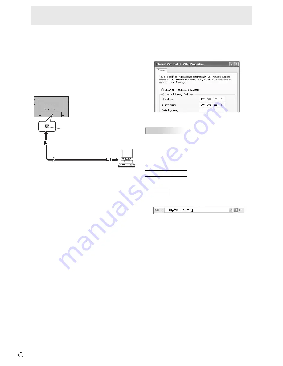
(1) Connecting your monitor to a PC

Connect a commercially available crossover LAN cable 
(UPT cable, Category 5) to the LAN  port on the PC and this 
monitor.

LAN cable (commercially available, crossover) 

To LAN terminal 

PC 

LAN terminal

(2) Specifying the PC’s IP address

To con

fi

 gure the monitor’s LAN settings, you must temporarily 

change the settings on the PC. 
This explanation is based on Windows XP.
1.  Log on to the PC with an administrator account. 
2.  Click [Start], and then click “Control Panel”.
3.  Click “Network and Internet Connections”, and then click 

“Network Connections”. 
If you are using the classic display style, double-click on 
“Network Connections”.

4.  Right click on “Local Area Connection” and from the menu, 

click “Properties”.

5.  Click “Internet Protocol (TCP/IP)”, and then click 

“Properties”.

6.  Make a note of the current IP address, subnet mask, and 

default gateway settings. 
Make sure you write this information now as you will 
be changing the IP address, subnet mask, and default 
gateway settings back to these settings afterwards. 

7.  Temporarily change the IP address and subnet mask. 

To access the monitor as it is shipped from the factory, set 
as follows. 

• IP Address: 192.168.150.3
•  Subnet Mask: 255.255.255.0
•  Default Gateway: (leave blank)

8.  Click [OK] and then reboot the PC.

TIPS

•  This monitor is factory preset as shown below. 
 IP 

Address 

192.168.150.2

  Subnet Mask 

: 255.255.255.0

  Default Gateway  : 0.0.0.0

(3) Con

fi

 guring the monitor’s LAN settings

Access the monitor using Internet Explorer. 

Controlling the monitor

1.  Turn the power ON to the monitor.
2.  Set RS-232C/LAN SELECT on the SETUP menu to LAN. 

PC operation

3.  Launch Internet Explorer, in the “Address” box type 

“http://192.168.150.2/” and press the Enter key. 

You will be prompted to enter a user name and password. 

4.  Leave the user name and password boxes blank and click 

[OK]. 

Controlling the Monitor with a PC (LAN)

Summary of Contents for LDT521V

Page 1: ...OPERATION GUIDE 52 ...

Page 2: ...roduced and sold by RICOH COMPANY LTD All other brand and product names are trademarks or registered trademarks of their respective holders Language of OSD menu used in this manual is English by way of example Illustrations in this manual may not exactly represent the actual product or display This manual assumes use in horizontal orientation except where specifically noted Contents Basic Operatio...

Page 3: ... menu when the menu screen is not displayed B R I G H T 15 Press or to adjust the brightness If you do not press any buttons for about 4 seconds the BRIGHT menu automatically disappears 6 SIZE Screen size selection The menu is displayed Press or to select the screen size See page 4 7 DISPLAY Displays monitor information Every time you press this button the display changes from INFORMATION 1 INFORM...

Page 4: ...his monitor s screen size switching or dual screen display functions to compress or expand the screen for commercial or public viewing in establishments like cafes or hotels may infringe on the rights of the creators as protected by Copyright Law so please be careful When Enlarge is set the screen size is fixed to WIDE mode When dual screen display is selected the screen size cannot be changed The...

Page 5: ...V 60 Hz H 66 3 kHz 4 Press or to adjust the setting AUTO CONTRAST BLACK LEVEL TINT COLORS SHARPNESS 40 96 30 30 12 1 2 PICTURE SCREEN PICTURE AUDIO SETUP OPTION ENLARGE PIP PbyP OK MENU V 60 Hz H 66 3 kHz PC3 D SUB 1 9 2 0 x 1 0 8 0 For items that have press make settings and then press MENU 5 Press MENU twice to close the menu screen TIPS The menu will differ depending on the input mode The menu ...

Page 6: ...rforms adjustment CONTRAST Adjusts the brightness of the image BLACK LEVEL Adjusts the entire brightness of the video signals TINT Adjusts the hue Selecting changes the color towards green and selecting changes it towards magenta COLORS Adjusts the color intensity SHARPNESS Adjusts the sharpness of the image ADVANCED AV input You can adjust more specifically See page 10 COLOR MODE Changes the colo...

Page 7: ...value has 1 to 3 digits the empty digit s from the left is filled with a one byte space s ID No SET Assigns ID numbers to monitors connected in a daisy chain see page 13 using RS 232 cables The numbers 1 to 255 are available for ID numbers If 0 is set the system regards this as the state where no ID number is set LAN SETUP Configures the settings to control the monitor from the computer via LAN Se...

Page 8: ... be set COLOR SYSTEM AV4 AV5 Select the color system of the AV equipment which is connected to AV4 and AV5 input terminal AUTO PAL PAL 60 SECAM NTSC3 58 NTSC4 43 When AUTO is selected the color system is automatically set according to the input signal ENLARGE PC input ENLARGE H Sets the number of screen splits number of monitors in the horizontal direction used for the enlargement See page 9 ENLAR...

Page 9: ...ially available is required When connected in PC2 PC3 PC4 a splitter for the video signal commercially available is required When Enlarge is used the AUTO INPUT CHANGE function is disabled When Enlarge is used the SCREEN MOTION function is disabled To cancel the enlargement set 1 for ENLARGE H and ENLARGE V respectively SCHEDULE You can set the time to switch the monitor on and off Set this functi...

Page 10: ... with 6 colors of R red Y yellow G green C cyan B blue and M magenta TIPS When FLESH TONE is set to LOW or HIGH C M S HUE SATURATION VALUE cannot be set Adjustments for PC screen display Automatic adjustment When you use the PC3 input terminal or PC4 input terminals to display a PC screen for the first time or when you change the setting of the PC use the automatic screen adjustment 1 Switch the i...

Page 11: ...ly the FUNCTION operation is enabled Disables all operations other than FUNCTION not even power on off RS 232C LAN Specifies whether to allow control via RS 232C or LAN see pages 12 and 21 OSD DISPLAY Hides shows menus The FUNCTION screen cannot be hidden LED Specifies whether to light power LEDs Initialization Reset Functional Restriction Setting TEMPERATURE ALERT Selects the notification method ...

Page 12: ...ommercially available First monitor Second monitor PC To COM port RS 232C output terminal RS 232C input terminal Communication conditions Set the RS 232C communication settings on the PC to match the monitor s communication settings as follows Baud rate 9600 bps Stop bit 1 bit Data length 8 bits Flow control None Parity bit None Communication procedure Command format When a command is sent from th...

Page 13: ...HV When control via RS 232C is locked to prevent use using the operation lock function see page 11 E C D K O L Return code 0DH 0AH When RS 232C LAN SELECT is set to LAN U N S E L E C T E D Return code 0DH 0AH Communication interval After OK or ERR is returned you must send the following commands To set a timeout for the command response specify 10 seconds or longer Provide an interval of 100 ms or...

Page 14: ...or with ID number 2 VOLM0020 Sets volume to 20 OK 001 The volume of the monitor with ID number 1 the one directly connected to the PC is set to 20 The IDSL command is effective only once for the immediately succeeding command IDLK The parameter of this command sets the ID number of the monitor The monitor is subject to all subsequent commands Example IDLK0002 Following commands are for the monitor...

Page 15: ...ll the connected monitors If you want to determine that a value has been returned by a specific set assign ID numbers to each monitor in advance When some monitors do not return their responses the probable cause is that the monitors could not receive the command or command processing is not complete Do not send a new command Example When 4 monitors are connected and assigned ID numbers 1 through ...

Page 16: ...ERR when AV1 DVI D is selected for DVI SELECT 2 PC3 D SUB 3 AV3 COMPONENT ERR when PC4 RGB is selected for BNC SELECT 4 AV5 VIDEO 6 PC4 RGB ERR when AV3 COMPONENT is selected for BNC SELECT 7 AV1 DVI D ERR when PC1 DVI D is selected for DVI SELECT 8 AV4 S VIDEO 9 AV2 HDMI ERR when PC2 HDMI is selected for HDMI SELECT 10 PC2 HDMI ERR when AV2 HDMI is selected for HDMI SELECT R 1 PC1 DVI D A 2 PC3 D...

Page 17: ... Y CMSG G CMSC C CMSB B CMSM M CRST W 2 Resets the saturation C M S VALUE CMVR WR 10 10 10 10 R CMVY Y CMVG G CMVC C CMVB B CMVM M CRST W 3 Resets the brightness COLOR MODE BMOD WR 0 0 STD B 2 2 VIVID 3 3 sRGB When the input mode is PC WHITE BALANCE THRU CTMP WR 0 0 When the input mode is PC1 PC2 B PRESET 1 15 1 15 From 1 approximately 3 000K to 15 approximately 10 000K 500K steps USER 99 99 R CON...

Page 18: ...OPTION menu Function Command Direction Parameter Reply Control Response contents DATE TIME SETTING DATE WR AABBCCDDEE AABBCCDDEE AA Year BB Month CC Day DD Time EE Minute B SCHEDULE SC01 SC08 WR ABCDEFFGGH ABCDEFFGGH Schedule of a specified number A Schedule 0 Not effective 1 Effective B Power 0 OFF 1 ON C Day of the week 1 0 Only once 1 Every week 2 Every day D Day of the week 2 0 Sunday 1 Monday...

Page 19: ...TION 4 x 4 EPOS WR 0 15 0 15 IMAGE POSITION 5 x 5 EPOS WR 0 24 0 24 ENLARGED SCREEN POSITIONING THE LONGEST DIRECTION EPSH WR 999 999 999 999 The setting range depends on the ENLARGE MODE setting and the IMAGE POSITION THE SHORTEST DIRECTION EPSV WR 999 999 999 999 ENLARGE IMAGE POSITION SETTING ESTG WR XXYY XXYY XX ENLARGE MODE Same as EMAG YY IMAGE POSITION Same as EPOS ESHV WR XXYY XXYY XX ENLA...

Page 20: ...ON 1 OFF B LED OFLD WR 0 1 0 1 0 ON 1 OFF B TEMPERATURE ALERT TALT WR 0 2 0 2 0 OFF 1 OSD LED 2 LED B STATUS ALERT SALT WR 0 2 0 2 0 OFF 1 OSD LED 2 LED B Others Function Command Direction Parameter Reply Control Response contents SCREEN SIZE PC WIDE WR 1 5 1 5 1 WIDE 2 NORMAL 3 Dot by Dot 4 ZOOM1 5 ZOOM2 B SCREEN SIZE AV WIDE WR 1 5 1 5 1 WIDE 2 ZOOM1 3 ZOOM2 4 NORMAL 5 Dot by Dot B VOLUME VOLM W...

Page 21: ...se settings can be made on either the monitor or a PC connected to the monitor The settings depend on the configuration of your LAN Ask your LAN administrator for details To set on the monitor Set RS 232C LAN SELECT on the SETUP menu to LAN and then set the LAN SETUP options See page 7 After setting each item select SET and press MENU DHCP CLIENT If your LAN has a DHCP server and you wish to obtai...

Page 22: ...roperties 5 Click Internet Protocol TCP IP and then click Properties 6 Make a note of the current IP address subnet mask and default gateway settings Make sure you write this information now as you will be changing the IP address subnet mask and default gateway settings back to these settings afterwards 7 Temporarily change the IP address and subnet mask To access the monitor as it is shipped from...

Page 23: ...sic operation You use Internet Explorer on a PC on the LAN to control the monitor 1 Launch Internet Explorer on the PC 2 In the Address box type http followed by your monitor s IP address followed by then press the Enter key When prompted to enter a user name and password type the user name and password that you specified in the security settings see page 25 and click OK If you did not make any se...

Page 24: ...3 TIPS In standby mode Power ON is the operation available ADJUSTMENT You can adjust these settings which are also available on the monitor s menu SCREEN See page 6 PICTURE See Page 6 PICTURE ADVANCED See Page 6 AUDIO See page 6 SETUP See page 7 OPTION See page 7 SCHEDULE See page 9 ENLARGE See page 9 PIP PbyP See page 8 FUNCTION See page 11 Controlling the Monitor with a PC LAN ...

Page 25: ...SETUP settings to the factory preset values except for the DNS SERVER setting NETWORK SECURITY This screen allows you to specify the security related settings USER NAME PASSWORD Sets up a user name and password to restrict access to this monitor After entering a user name and password click Apply ACCEPT IP ADDRESS You can limit access to this monitor by registering IP addresses of PCs that should ...

Page 26: ...tion of your LAN Ask your LAN administrator for details SMTP SERVER Specify the SMTP server address for sending e mail When using a domain name make sure to specify the DNS server as well See page 25 ORIGINATOR E MAIL ADDRESS Specify the e mail address for this monitor This address becomes the e mail address of the originator ORIGINATOR NAME Specify the name for the originator This name appears in...

Page 27: ...n this option is checked a log is added to the mail which notifies a temperature or status error TIPS The RECIPIENT E MAIL ADDRESSES can be up to 64 alphanumeric characters or symbols Controlling the Monitor with a PC LAN MAIL PERIODICAL When PERIODICAL for CONDITION of MAIL RECIPIENT is checked set the date and time to send the mail DAY OF THE WEEK Specify the day of the week to send the periodic...

Page 28: ...N Enter a URL to display when an error occurs on the monitor Up to 64 alphanumeric characters or symbols can be used CONDITION Specify the condition to display the URL CONFIRMATION The home page of the specified URL is displayed You can check whether the URL you entered is correct TIPS It is also possible to specify the message text such as the name of a contact or a telephone number to be display...

Page 29: ...M E M O 29 E ...

Page 30: ...aly Sales Phone 39 0 39 60531 Fax 39 0 39 6053214 E mail info projector it mee com MEU NL MitsubishiElectric Europe B V Benelux Branch http www MitsubishiElectric nl Nijverheidsweg 23a 3641 RP Mijdrecht The Netherlands Sales Phone 31 297 282461 Fax 31 297 283936 E mail info mitsubishi nl Technical Phone 31 297 282461 Fax 31 297 283936 E mail info mitsubishi nl MEU MITSUBISHI ELECTRIC EUROPE B V ht...

Reviews: