7 - 38
7.5 PLC Side Setting
POINT
POINT
POINT
(1) When the [intelligent function module switch setting] has been set
After writing PLC parameters to the PLC CPU, turn the PLC CPU OFF then back ON again,
or reset the PLC CPU.
(2) Connection of multiple GOTs
To some serial communication module models, two GOTs can be connected using both CH1
and CH2.
(3) When connecting to the modem interface module
When the modem interface module is connected, only CH2 can be used.
7.5.3
Connecting serial communication module (QnA Series)
POINT
POINT
POINT
Serial communication module (QnA Series)
For details of the serial communication module (QnA Series), refer to the following manual.
➠
Serial Communication Module User's Manual (Modem Function Additional Version)
■1.
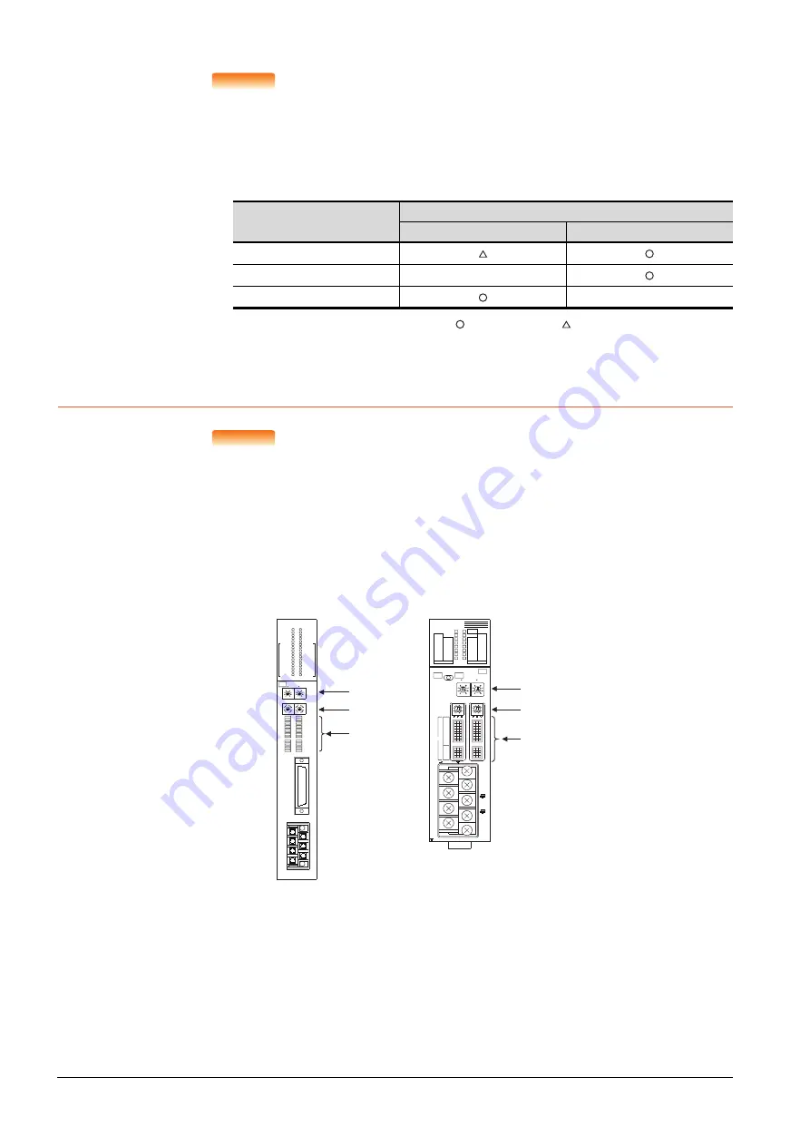
Switch setting on serial communication module
Set the Station number switches, the Mode setting switch for the channel used for GOT connection, and the
Transmission specifications switches.
Model
Connection of 2 GOTs
Function version A
Function version B
QJ71C24(-R2)
QJ71C24N(-R2/R4)
-
LJ71C24(-R2)
-
: 2 GOTs connectable, : 1 GOT connectable, -: Not applicable
A
J71QC24N
RUN
CPUR/W
NEU
ACK
NAK
C/N
P/S
PRO
SIO
SD.WAIT
SD
RD
CH1.ERR.
CH2.ERR.
NEU
ACK
NAK
C/N
P/S
PRO
SIO
SD.WAIT
SD
RD
CH.1
CH.2
1
CH1
CH2
STATION
No.
MODE
SW
01
02
03
04
05
06
07
08
09
10
11
12
RDA
RDB
SG
SDA
SDB
NC
FG
CH1
RS-232C
CH2
RS422
RS485
8
4
0
C
8
4
0
C
5
0
5
0
10
AJ71QC24N, AJ71QC24N-R2,
AJ71QC24N-R4,AJ71QC24,
AJ71QC24-R2, AJ71QC24-R4
(3)
(1)
(2)
A
1SJ71QC24N
CH1
ERR.
C/N
P/S
PRO
SID
CH2
ERROR
RD
SW.E
NEU
ACK
NAK
SD.W.
SD
STS
ERR.
DISPLAY
5
0
5
0
CH1
CH2
10
1
STATION NO.
MODE
A1SJ71QC24N
RUN
RD
C.R/W
NEU
ACK
NAK
SD.W.
SD
ERR.
C/N
P/S
PRO
SIO
AB
CH1 RS-232-C
CH2 RS-422/RS-485
SG
(FG)
(NC)
SDA
SDB
RDA
RDB
8
4
0
C
8
4
0
C
ON
2
1
4
3
6
5
8
7
10
9
12
11
SW
(1)
(3)
(2)
A1SJ71QC24N1, A1SJ71QC24N1-R2,
A1SJ71QC24N, A1SJ71QC24N-R2,
A1SJ71QC24, A1SJ71QC24-R2
Summary of Contents for GOT2000 Series
Page 2: ......
Page 84: ......
Page 432: ...6 58 6 6 Precautions ...
Page 578: ...9 54 9 6 Precautions ...
Page 726: ...12 84 12 5 Precautions ...
Page 756: ......
Page 822: ...14 66 14 4 Device Range that Can Be Set ...
Page 918: ...15 96 15 7 Precautions ...
Page 930: ...16 12 16 6 Precautions ...
Page 964: ......
Page 1002: ...19 38 19 7 Precautions ...
Page 1022: ...20 20 20 5 Precautions ...
Page 1023: ...MULTI CHANNEL FUNCTION 21 MULTI CHANNEL FUNCTION 21 1 ...
Page 1024: ......
Page 1054: ...21 30 21 5 Multi channel Function Check Sheet ...
Page 1055: ...FA TRANSPARENT FUNCTION 22 FA TRANSPARENT FUNCTION 22 1 ...
Page 1056: ......
Page 1223: ......


