


7
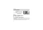
PRE-OPERATION INSTRUCTIONS
1.3
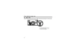
Parts
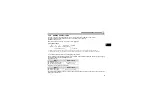
Front view
Rear view
0
9
8
7
6
5
4
3
2
1
X10
SW1
0
9
8
7
6
5
4
3
2
1
X1
SW2
SW3
D1 D2
D3 D4
FR-A7NF
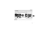
Mounting
hole
LED (operation status indication)
Lit/flicker/OFF of the LED indicate inverter
operation status.
Mounting
hole
Connector
Connect to the inverter option connector.
Node address switch
Set the node address.
Mounting
hole
Connector for communication
Connect to the network by
connecting a FL-net dedicated
cable.
Switch for manufacturer
setting
Do not change from
initially-set status (OFF).
SW3
O
N
2
L
(Refer to page 8)
(Refer to page 16)
Summary of Contents for FR-F740-01160-EC
Page 103: ...97 MEMO ...


