Parameter
Communication operation and settings
FR-D700 SC EC
6 - 237
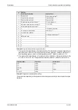
The signal within parentheses is the default setting. The description changes depending on
the setting of Pr. 180 to Pr. 182 "Input terminal function selection". (Refer to section 6.9.1.)
Each assigned signal is valid or invalid depending on NET. (Refer to section 6.17.3.)
The signal within parentheses is the default setting. Definitions change according to the
Pr. 190, Pr. 192 or Pr. 197 "Output terminal function selection". (Refer to section 6.9.5.)
The restrictions depending on the operation mode changes according to the computer link spec-
ifications.
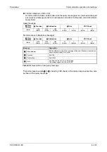
Bit
Definition
Control Input Instruction
Inverter Status
0
Stop command
RUN (inverter running)
1
Forward rotation command
Forward rotation
2
Reverse rotation command
Reverse rotation
3
RH (high speed operation command)
SU (up to frequency)
4
RM (middle speed operation command)
OL (overload)
5
RL (low speed operation command)
0
6
0
FU (frequency detection)
7
RT (second function selection)
ABC (Alarm)
8
AU (current input selection)
0
9
0
SO (Safety monitor output)
10
MRS (output stop)
0
11
0
0
12
0
0
13
0
0
14
0
0
15
0
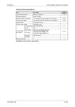
Alarm
Tab. 6-80:
Inverter status/control input instruction
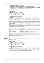
Operation Mode
Read Value
Written Value
EXT
H0000
H0010
PU
H0001
—
EXT JOG
H0002
—
NET
H0004
H0014
PU + EXT
H0005
—
Tab. 6-81:
Operation mode/inverter setting
Summary of Contents for FR-D720S SC EC
Page 2: ......
Page 4: ......
Page 24: ...Description of the case Product checking and part identification 1 4 ...
Page 108: ...Operation panel Operation 4 20 ...
Page 436: ...Setting for the parameter unit and operation panel Parameter 6 286 ...
Page 484: ...Measurements on the main circuit Maintenance and inspection 8 14 ...
Page 504: ...Specification change Appendix A 20 ...
Page 505: ......
Page 506: ......
Page 510: ...Index Appendix A 24 ...
Page 511: ......


