Function assignment of external terminals
Parameter
6 - 94
6.9.4
Start signal selection (Terminal STF, STR, STOP, Pr. 250)
You can select the operation of the start signal (STF/STR).
Used to select the stopping method (deceleration to a stop or coasting) when the start signal
turns off. Used to stop the motor with a mechanical brake, etc. together with switching off of the
start signal. (Refer to section 6.8.3 for stop selection.)
The above parameter can be set when Pr. 160 = 0.
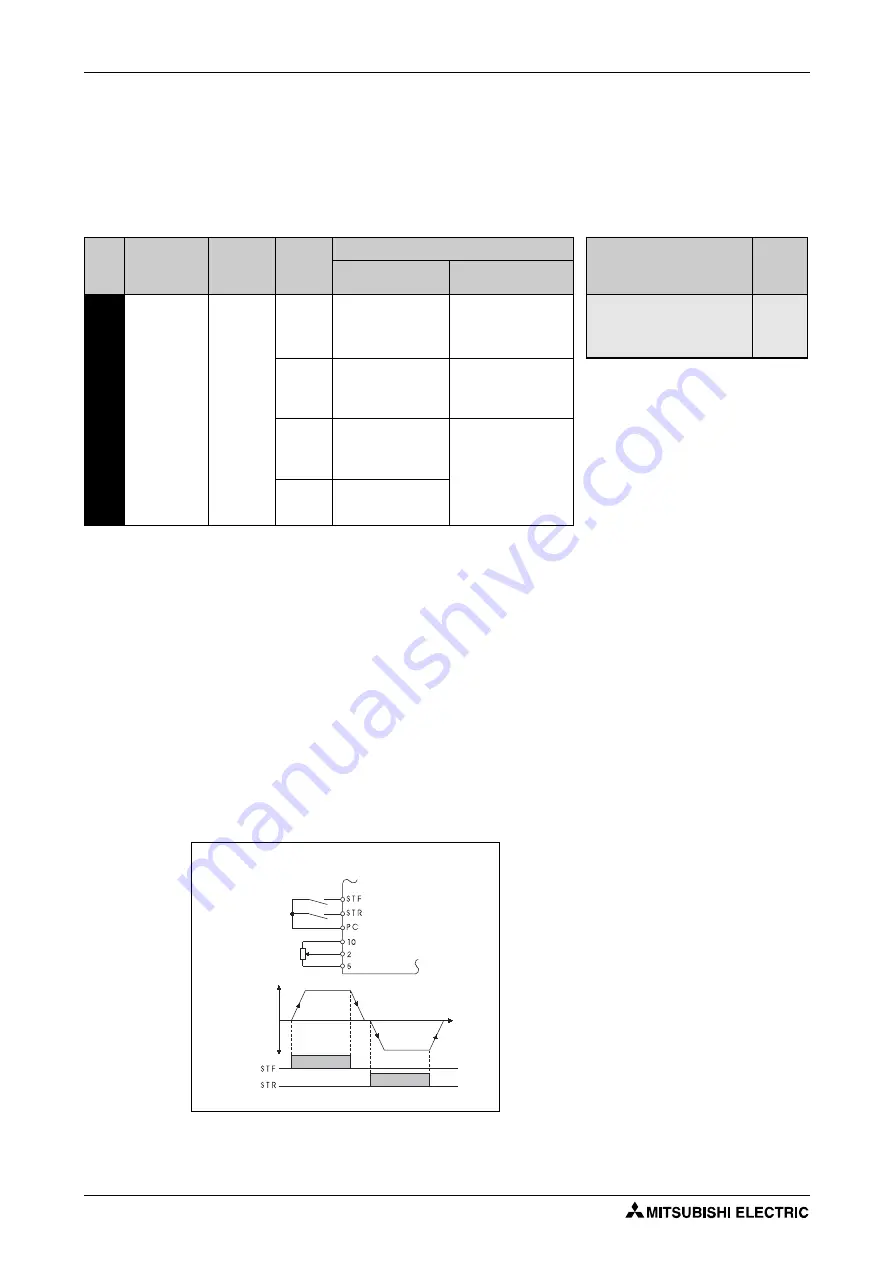
2-wire type (terminals STF and STR)
A two-wire type connection is shown below.
In the initial setting, the forward/reverse rotation signals (STF/STR) are used as start and stop
signals. Turn on either of the forward and reverse rotation signals to start the motor in the cor-
responding direction. If both are turned off (or on) during operation, the inverter decelerates to
a stop.
The speed setting signal may either be given by entering 0 to 10V DC across the speed setting
input terminal 2-5, by setting the required values in Pr. 4 to Pr. 6 "Multi-speed setting" (high, mid-
dle, low speeds), etc. (For multi-speed operation, refer to section 6.5.1).
When Pr. 250 is set to any of "1000 to 1100, 8888", the STF signal becomes a start command
and the STR signal a forward/reverse command.
Pr.
No.
Name
Initial
Value
Setting
Range
Description
Parameters referred to
Refer to
Section
Start Signal
(STF/STR)
Stop Operation
250
Stop selection
9999
0–100s
STF: Forward
rotation start
STR: Reverse rotation
start
The motor is coasted to
a stop when the preset
time elapses after the
start signal is turned off.
4–6
178–182
Multi-speed
setting
Input terminal
function selection
1000s
–
1100s
STF: Start signal
STR: Forward/reverse
signal
The motor is coasted to
a stop (Pr. 250
−
1000)s
after the start signal is
turned off.
9999
STF: Forward
rotation start
STR: Reverse
rotation start
When the start signal is
turned off, the motor
decelerates to stop.
8888
STF: Start signal
STR: Forward/reverse
signal
Fig. 6-47:
2-wire type connection (Pr. 250 = 9999)
I001148E
Forward rotation start
Reverse rotation start
Inverter
Output frequency
Fo
rw
a
rd
rot
a
tion
Re
v
e
rse
rotation
Time
ON
ON
Summary of Contents for FR-D720S SC EC
Page 2: ......
Page 4: ......
Page 24: ...Description of the case Product checking and part identification 1 4 ...
Page 108: ...Operation panel Operation 4 20 ...
Page 436: ...Setting for the parameter unit and operation panel Parameter 6 286 ...
Page 484: ...Measurements on the main circuit Maintenance and inspection 8 14 ...
Page 504: ...Specification change Appendix A 20 ...
Page 505: ......
Page 506: ......
Page 510: ...Index Appendix A 24 ...
Page 511: ......


