


124
Function assignment of external terminal and control
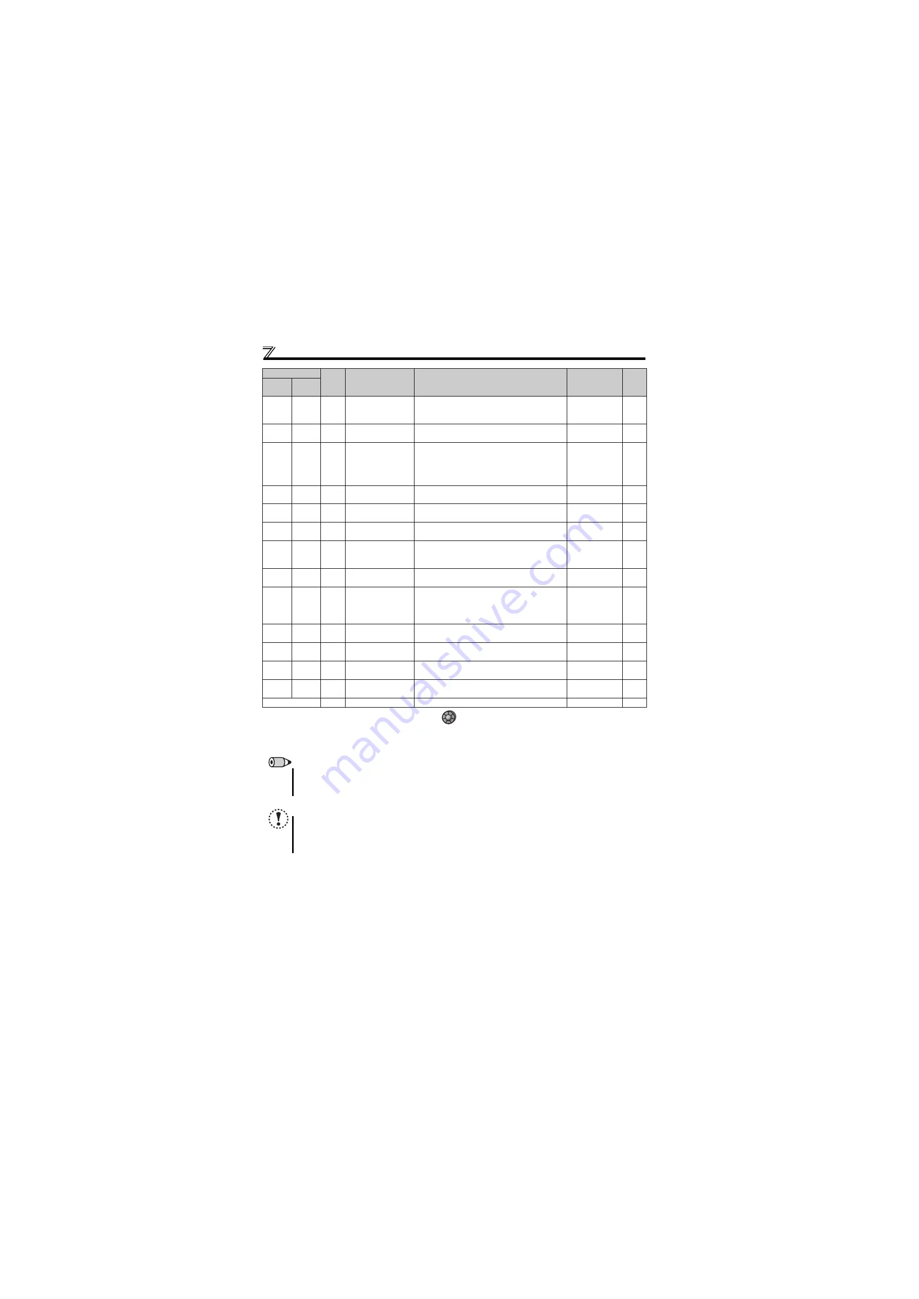
37
137
RY3
Operation ready 3
Output during pre-excitation and operation.
Turned OFF during interlock operation with the BOF
signal.
Pr. 281, Pr. 283
,
47
147
PID
During PID control
activated
Output during PID control.
Pr. 127 to Pr. 134,
Pr. 575 to Pr. 577
48
148
Y48
PID deviation limit
Output when the absolute value of deviation exceeds
the limit value.
Pr. 127 to Pr. 134,
Pr. 241, Pr. 553,
Pr. 554,
Pr. 575 to Pr. 577,
C42 to C45
64
164
Y64
During retry
Output during retry processing.
Pr. 65,
Pr. 67 to Pr. 69
70
170
SLEEP PID output interruption
Output when the PID output interruption function is
executed.
Pr. 127 to Pr. 134,
Pr. 575 to Pr. 577
79
179
Y79
Pulse train output of
output power
Output in pulses every time the accumulated output
power of the drive unit reaches the
Pr. 799
setting.
Pr. 799
90
190
Y90
Life alarm
Output when any of the control circuit capacitor, main
circuit capacitor and inrush current limit circuit or the
cooling fan approaches the end of its service life.
Pr. 255 to Pr. 259
91
191
Y91
Fault output 3
(power-OFF signal)
Output when a fault occurs due to the internal circuit
failure or the drive unit wiring mistake.
—
93
193
Y93
Current average
monitor signal
Average current value and maintenance timer value
are output as pulses.
The signal cannot be set in
Pr. 192 A,B,C terminal
function selection
.
Pr. 555 to Pr. 557
95
195
Y95
Maintenance timer
signal
Output when
Pr. 503
rises to or above the
Pr. 504
setting.
Pr. 503, Pr. 504
96
196
REM
Remote output
Output to the terminal when a value is set to the
parameter.
Pr. 495, Pr. 496
98
198
LF
Alarm output
Output when an alarm (fan failure or communication
error warning) occurs.
Pr. 121, Pr. 244
99
199
ALM
Fault output
Output when a fault occurs.
The signal output is stopped when the fault is reset.
—
9999
—
No function
—
—
—
Note that when the speed setting is varied using an analog signal or
of the operation panel, the output of the SU (up to speed) signal may alternate
ON and OFF depending on that varying speed and the timing of the varying speed due to acceleration/deceleration time setting.
(The output will not alternate ON and OFF when the acceleration/deceleration time setting is "0s".)
REMARKS
The same function may be set to more than one terminal.
When the function is executed, the terminal conducts at the setting of any of "0 to 99", and does not conduct at the setting of
any of "100 to 199".
NOTE
Changing the terminal assignment using
Pr. 190
and
Pr. 192 (output terminal function selection)
may affect the other
functions. Set parameters after confirming the function of each terminal.
Do not assign signals which repeat frequent ON/OFF to A, B, and C. Otherwise, the life of the relay contact decreases.
The common terminal for terminal RUN is terminal SE.
Setting
Signal
Function
Operation
Related
Parameter
Refer
to
Page
Positive
logic
Negative
logic
Summary of Contents for FR-D720-0.2K-G
Page 45: ...34 MEMO ...
Page 293: ...290 MEMO ...


