26
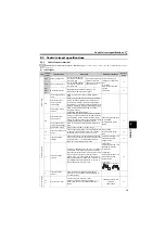
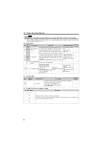
Control circuit specifications
2.3.5
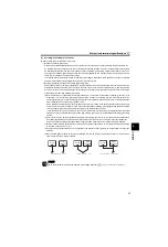
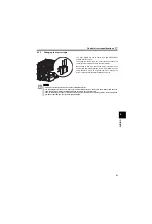
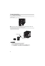
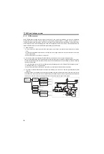
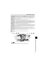
Connection to the PU connector
Using the PU connector, you can perform communication operation from the FR-PU07, enclosure surface operation panel or
a personal computer etc.
Remove the inverter front cover when connecting.
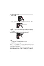
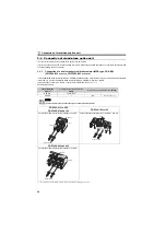
When connecting the parameter unit, enclosure surface operation panel using a connection cable
Use the optional FR-CB2
or connector and cable available on the market.
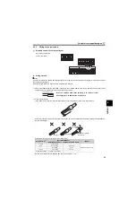
Insert the cable plugs securely into the PU connector of the inverter and the connection connector of the FR-PU07, FR-PA07
along the guide until the tabs snap into place.
Install the inverter front cover after connecting.
REMARKS
Overall wiring length when the parameter unit is connected: max 20m
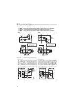
Refer to the following when fabricating the cable on the user side.
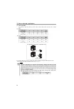
Examples of product available on the market (as of February, 2008)
Parameter unit connection cable
(FR-CB2
)(option)
PU connector
STF FWD PU
FR-PU07
FR-PA07
Product
Type
Maker
1)
10BASE-T cable
SGLPEV-T 0.5mm
×
4P
Mitsubishi Cable Industries, Ltd.
Summary of Contents for FR-D700 Series
Page 11: ...VII MEMO ...
Page 23: ...12 MEMO ...
Page 57: ...46 MEMO ...
Page 262: ...258 MEMO ...
Page 276: ...272 MEMO ...
Page 287: ...283 MEMO ...
Page 289: ......


