background image

FAILSAFE SYSTEM WHICH USES THE INVERTER

13

3

FAILSAFE SYSTEM WHICH USES THE INVERTER

When a fault is detected by the protective function, the protective function activates and output a Fault (ALM) signal.  However, a fault signal may not be output at 
an inverter's fault occurrence when the detection circuit or output circuit fails, etc. Although Mitsubishi Electric assures the best quality products, provide an 
interlock which uses inverter status output signals to prevent accidents such as damage to the machine when the inverter fails for some reason. Also, at the same 
time consider the system configuration where a failsafe from outside the inverter, without using the inverter, is enabled even if the inverter fails.

Interlock method which uses the inverter status output signals

By combining the inverter output signals to provide an interlock as shown below, an inverter failure can be detected.

Backup method outside the inverter

Even if the interlock is provided by the inverter status signal, enough failsafe is not ensured depending on the failure status of the inverter itself. For example, if an 
inverter CPU fails in a system interlocked with the inverter's fault, start, and RUN signals, no fault signal will be output and the RUN signal will be kept ON 
because the inverter CPU is down.
Provide a speed detector to detect the motor speed and current detector to detect the motor current and consider the backup system such as performing a check 
as below according to the level of importance of the system.

 • Start signal and actual operation check
Check the motor running and motor current while the start signal is input to the inverter by comparing the start signal to the inverter and detected speed of the 
speed detector or detected current of the current detector. Note that the current is flowing through the motor while the motor coasts to stop, even after the 
inverter's start signal is turned OFF. For the logic check, configure a sequence considering the inverter's deceleration time. In addition, it is recommended to check 
the three-phase current when using the current detector.

 • Command speed and actual operation check
Check for a gap between the actual speed and commanded speed by comparing the inverter's speed command and the speed detected by the speed detector.

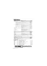
Interlock method

Check method

Used signals

Refer to

Inverter protective function 
operation

Operation check of an alarm contact.
Circuit error detection by negative logic.

Fault (ALM) signal

Chapter 5 of the FR-A800 
Instruction Manual (Detailed)

Inverter operating status

Operation ready signal check.

Operation ready (RY) signal

Chapter 5 of the FR-A800 
Instruction Manual (Detailed)

Inverter running status

Logic check of the start signal and running 
signal.

Start signal (STF signal, STR signal)
Inverter running (RUN) signal

Chapter 5 of the FR-A800 
Instruction Manual (Detailed)

Inverter running status

Logic check of the start signal and output 
current.

Start signal (STF signal, STR signal)
Output current detection (Y12) signal

Chapter 5 of the FR-A800 
Instruction Manual (Detailed)

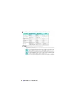
Inverter

Controller

System failure

To the alarm detection sensor

Sensor

(speed, temperature,

air volume, etc.)

Summary of Contents for FR-B-750

Page 1: ...は ご使用いただく場合の取扱い 留意点について述べて あります 機器の知識 安全の情報そして注意事項のすべてについて習熟してからご使用ください なお この取扱説明書 導入編 と同梱CD ROMは ご使用になるお客様の手元に届くようご配慮をお願いい たします Thank you for choosing this Mitsubishi Electric pressure resistant explosion proof motor driving inverter This Instruction Manual Startup and the enclosed CD ROM give handling information and precautions for use of this product Do not use this product until you have a fu...

Page 2: ...として区分してあります 取扱いを誤った場合に 危険な状況が起こりえ て 死亡または重傷を受ける可能性が想定される 場合 取扱いを誤った場合に 危険な状況が起こりえ て 中程度の傷害や軽傷を受ける可能性が想定さ れる場合および物的損害だけの発生が想定される 場合 なお に記載した事項でも 状況によっては重大な結 果に結びつく可能性があります いずれも重要な内容を記載してい ますので必ず守ってください 警告 注意 注意 警告 インバータ通電中は表面カバーや配線カバーを外さないでください ま た 表面カバーや配線カバーをはずした状態で運転しないでください 高電圧の端子および充電部が露出していますので感電の原因となります 電源 OFF 時でも配線作業 定期点検以外では表面カバーをはずさないで ください インバータ内部は充電されており感電の原因となります 配線作業や点検は 操作パネルの表示が消灯した...

Page 3: ...たくん蒸成分が弊社製品に侵入しない ように注意するか くん蒸以外の方法 熱処理など で消毒 除虫対策 をしてください なお 木製梱包材の消毒 除虫対策は梱包前に実施し てください 配線について インバータの出力側には 進相コンデンサやサージ吸収器 ラジオノイ ズフィルタを取り付けないでください 過熱 焼損の恐れがあります 出力側 端子 U V W は正しく接続してください モータが逆回転に なります 試運転調整について FREQROL B3 シリーズはオフラインオートチューニング実施後 アド バンスト磁束ベクトル制御で運転してください 運転前に各パラメータの確認 調整を行ってください 機械によっては 予期せぬ動きとなる場合があります 警告 使用方法について このインバータは 三菱電機インバータ駆動用耐圧防爆形モータとの組 合せで使用しますので 駆動モータとのペアセットに注意してください こ...

Page 4: ...を貼り付けてください リトライ機能を選択した場合 瞬停再始動を選択した場合 一般的注意 本取扱説明書に記載されている全ての図解は 細部を説明するためにカ バーまたは安全のための遮断物を取り外した状態で描かれている場合が ありますので 製品を運転するときは必ず規定どおりのカバーや遮断物 を元どおりに戻し 取扱説明書に従って運転してください 注意 リ トライ機能 選択中 モータ 機械に近寄らないでく だ さい アラーム発生時に突然 所 定時間経過後 始動します 注意 瞬停再始動 選択中 モータ 機械に近寄らないでく だ さい 瞬時停電発生時に突然 リ セッ ト時間経過後 始動します ...

Page 5: ...MEMO 4 ...

Page 6: ...らされる場所を避けてください インバータは不燃性の壁面に据え付けてください 複数台収納する場合は 並列に据え付けて冷却対策を行ってください インバータを据え付ける盤を設計または製作する場合は 盤に据え付ける機器類の発熱や使用場所の環境などを 十分考慮してください 3700 以下は 1cm 以上です 22K 以下は 周囲温度 40 以下で使用する場合には密着取付け 間隔 0cm できます 項目 内容 周囲温度 10 50 凍結のないこと 周囲湿度 90 RH 以下 結露のないこと 保存温度 20 65 雰囲気 屋内 腐食性ガス 引火性ガス オイルミスト じんあいのないこと 標高 2500m 以下 振動 5 9m s2 以下 10 55Hz X Y Z 各方向 FR H B3 3700 低騒音 記号 タイプ 標準 N なし 記号 内容 400 3700 5 5K 37K インバータ定格容量 W...

Page 7: ...ベクトル制御 不可 不可 可能 ベクトル制御 不可 不可 可能 PM モータ制御 不可 不可 可能 省エネ制御選択 不可 不可 可能 PWM 周波数 200V クラス 55K 以下 1kHz 200V クラス 75K 2kHz 400V クラス全容量 1kHz Pr 72 PWM 周波数選択 の設定 値変更可 FR B3 2kHz FR B3 N 14 5kHz 低騒音 Pr 72 PWM 周波数選択 の設定 値変更禁止 2kHz 初期値 Pr 72 PWM 周波数選択 の設定 値変更可 FR B 750 1500 2200 3700 5 5K 7 5K 11K 15K 22K 30K 37K 45K 55K 75K FR B3 400 750 1500 2200 3700 5 5K 7 5K 11K 15K 18 5K 22K 30K 37K FR A820 0 4K 0 75K 1 5...

Page 8: ...回路配線の入力側と出力側は分離してください 配線時にインバータ内部に電線の切りくずを残さないでください 電線の切りくずは 異常 故障 誤動作の原因になります インバータはいつもきれいにしてお いてください 制御盤などに取付け穴をあけるときは 切粉などがインバータに入らないよう注意してください 電圧 電流入力切換スイッチを適切に設定してください 設定が異なると異常 故障 誤動作の原因になります 3相交流電源 NFB 短絡片 R L1 S L2 T L3 R1 L11 S1 L21 PC DC24V電源 外部電源トランジスタ出力用コモン 正転始動 逆転始動 始動自己保持選択 中速 高速 低速 JOGモード 第2機能選択 出力停止 リセット 端子4入力選択 瞬停再始動選択 周波数設定信号 アナログ 10E 10V 10 5V 2 アナログコモン 2 3 1 補助入力 端子4入力 電流入力 1 4...

Page 9: ... B3 N 30K FR B3 N H30K FR B 37K 45K 200V クラス FR B3 N 37K FR B 55K 200V クラス FR B 37K 55K 400V クラス FR B3 N H37K FR B 75K 90K 400V クラス FR B 75K 200V クラス FR B 110K 400V クラス R L1 S L2 T L3 N P PR PX R1 L11 S1 L21 短絡片 短絡片 防爆専用モータ 電源 M チャージランプ M チャージランプ 短絡片 短絡片 防爆専用 モータ 電源 R L1 S L2 T L3 N P PR R1 L11 S1 L21 PX N P PR PX R1 L11 S1 L21 短絡片 短絡片 電源 M 防爆専用モータ チャージランプ R L1 S L2 T L3 N P PR R1 L11 S1 L21 電源 電源...

Page 10: ...5 5 5 5 5 5 5 5 5 5 5 5 5 5 5 FR B 7 5K FR B3 N 7 5K M5 M4 2 5 14 5 8 5 14 8 14 5 5 FR B 11K FR B3 N 11K M5 2 5 14 5 14 5 14 14 14 8 FR B 15K FR B3 N 15K M6 4 4 22 6 22 6 22 22 22 14 FR B3 N 18 5K M8 M6 7 8 38 8 38 8 38 38 38 14 FR B 22K FR B3 N 22K M8 M6 7 8 38 8 38 8 38 38 38 22 FR B 30K FR B3 N 30K M8 M6 7 8 60 8 60 8 60 60 60 22 FR B 37K FR B3 N 37K M10 M8 14 7 80 10 80 10 80 80 80 22 FR B 45K...

Page 11: ...る場合 配線の浮遊容量による充電電流の影響を受けて 過電流保護機能や高応答電流制限機能が誤動作したりインバータが故障する場合が あります 高応答電流制限が誤動作する場合は 機能を無効にしてください Pr 156 ストール防止動作選択 FR A800 取扱説明書 詳細編 5 章参照 Pr 72 PWM 周波数選択に関する詳細は FR A800 取扱説明書 詳細編 5 章を参照してください 制御回路用電源の電線サイズ 端子 R1 L11 S1 L21 端子ねじサイズ M4 電線サイズ 0 75 2mm2 締付トルク 1 5N m Pr 72 PWM 周波数選択 設定値 キャリア周波数 FR B 750 FR B 1500 以上 2 2kHz 以下 500m 500m 3 3kHz 以上 300m 500m 配線長 50m 以下 50m 100m 100m を超える PWM キャリア周波数 14...

Page 12: ...2 棒端子形式 メーカ名 圧着工具形名 お問い合わせ 絶縁スリーブ付 絶縁スリーブなし UL 電線用 0 3 AI 0 34 10TQ ー ー フエニックス コンタクト 株 CRIMPFOX 6 052 589 3810 0 5 AI 0 5 10WH ー AI 0 5 10WH GB 0 75 AI 0 75 10GY A 0 75 10 AI 0 75 10GY GB 1 AI 1 10RD A 1 10 AI 1 10RD 1000GB 1 25 1 5 AI 1 5 10BK A 1 5 10 AI 1 5 10BK 1000GB 0 75 2 本用 AI TWIN 2 0 75 10GY ー ー 電線サイズ mm2 棒端子品番 キャップ品番 メーカ名 圧着工具品番 お問い合わせ 0 3 0 75 BT 0 75 11 VC 0 75 株 ニチフ NH 69 052 857 272...

Page 13: ...側に接続してください 制御盤などに直接接地しないでください 異常出力端子 A1 B1 C1 A2 B2 C2 には リレーコイルやランプなどを必ず介してください トランジスタ出力用に外部電源を使用する場合 回り込み電流による誤作動が発生しないよう 以下の点に注意してください インバータの端子 SD を外部電源の 0V 端子とは接続しないでください シンクロジック インバータの端子 PC を外部電源の 24V 端子とは接続しないでください ソースロジック 端子 PC SD 間を DC24V 電源として使用する場合は インバータの外部に並列に電源を設置しないでください 詳細は取扱説明書 詳細編 2 章を参照してください 制御ロジック シンク ソース 切換 入力信号の制御ロジックを切り換えることができます 制御ロジックの切り換えは 制御回路基板上のジャンパコネクタの切り換えにより行います 使用す...

Page 14: ...出力されず RUN 信号は出力されたままということがあります システム重要度に応じて モータ速度を検出する速度検出器やモータ電流を検出する電流検出器を設け 下記のチェックを行うなどのバックアップシステム を検討してください 始動信号と実動作のチェック インバータへの始動信号と速度検出器の検出速度 または電流検出器の検出電流を比較し インバータへ始動信号を入力している時にモータが回転している ことやモータに電流が流れていることをチェックします なお 始動信号が OFF してもインバータが減速し モータが停止するまでの期間は モータは回転 しているため モータ電流も流れています 論理チェックは インバータの減速時間を考慮したシーケンスとしてください また 電流検出器を用いる場合 は 3相分の電流を確認されることを推奨します 指令速度と実動作速度のチェック インバータへの速度指令と速度検出器の検...

Page 15: ... 周辺回路不備による短絡の繰返し あるいは結線不備 モータの絶縁抵抗低下による地絡はインバータモジュールを破損することがありますのでイン バータ運転前には回路の絶縁抵抗を十分確認してください インバータ出力側の対地絶縁 相間絶縁は電源投入前に十分確認してください 特に古いモータの場合 雰囲気の悪い場所の場合にはモータの絶縁抵抗などの確認を確実に行ってください インバータ入力側の電磁接触器でインバータの始動 停止をしないでください 入力側電磁接触器による頻繁な開閉は 電源投入時の突入電流の繰り返しにより コンバータ部の寿命 開閉寿命は 100 万回程度 を短くするので 避 ける必要があります インバータの始動停止は必ず始動信号 STF STR 信号の ON OFF で行ってください 7 ページ参照 P PR 端子は外付けブレーキ抵抗器以外の機器を接続しないでください 機械式ブレーキは接続しな...

Page 16: ...が動作している場合に点灯します g FWD キー REV キー FWD キー 正転始動します 正転運転中は LED が点灯します REV キー 逆転始動します 逆転運転中は LED が点灯します 下記の場合は LED が点滅します 正転 逆転指令ありでも周波数指令がない場合 周波数指令が始動周波数以下の場合 MRS 信号が入力されている場合 h STOP RESET キー 運転指令を停止します 保護機能動作時は インバータのリセットを行います i M ダイヤル 三菱電機インバータのダイヤルを表します 周波数設定 パラメータの設定値を変更しま す 押すことで下記表示が可能です モニタモード時の設定周波数表示 Pr 992 で変更可能 校正時の現在設定値表示 アラーム履歴モード時の順番表示 j MODE キー 各モードを切り換えます と同時押しすることで運転モードの簡単設定モードへ移行します ...

Page 17: ...モリモードの詳細は FR A800 取扱説明書 詳細編 を参照してください パラメータ設定 ファンクション アラーム履歴 運転モー ド切換 周波数設定 モニタ 外部運転モー ド 1 電源投入時 出力周波数モニタ 電源投入時 2 5 PU運転モー ド 1 PUJOG運転モー ド 1 出力電流モニタ 2 出力電圧モニタ 2 数値変更 例 周波数設定が書込み完了 フ リ ッカー 過去8回分のアラームを表示することができます 最新のアラーム履歴には がつきます アラーム履歴の無い場合は を表示します 現在設定値 を表示 数値変更 パラメータ書込み完了 フ リ ッカー 例 例 例 例 パラ メ ータ コ ピー 初期値変更リ ス ト パラ メ ータ ク リ ア パラ メ ータオールク リ ア アラーム履歴ク リ ア ト レース機能 3 アラーム履歴1 4 アラーム履歴2 4 アラーム履歴8 4 機能別...

Page 18: ...5 80 モータ容量 インバータ定格容量 81 モータ極数 4 Pr 名 称 初期値 Pr 名 称 FR B FR B3 0 トルクブースト 1 上限周波数 必ず下記設定範囲内で使用 してください 22K 以下 0 120Hz 30K 以上 0 60Hz 3 基底周波数 10 直流制動動作周波数 11 直流制動動作時間 12 直流制動動作電圧 18 高速上限周波数 19 基底周波数電圧 30 回生機能選択 必ず下記設定範囲内で使用 してください 55K 以下 0 1 100 101 75K 以上 0 1 2 100 101 102 必ず下記設定範囲内で使用 してください 0 1 100 101 46 第 2 トルクブースト 60 省エネ制御選択 71 適用モータ 必ず下記設定範囲内で使用 してください 0 1 72 PWM 周波数選択 必ず下記設定範囲内で使用 してください 55K 以下 ...

Page 19: ...ンオートチューニングを実施した状態で防爆検定を 受けています 必ずモータを回転させるモードでオフラインオートチューニングを実施し アドバンスト磁束ベクトル制御 初期設定 で運転してく ださい アドバンスト磁束ベクトル制御とは 負荷トルクに見合ったモータ電流を流せるように電圧補正を行うことによって 低速トルクを向上させることができます また モータの実回転 数が速度指令値により近くなるように 出力周波数の補正 すべり補正 を行います 負荷の変動が激しい場合などに有効です オフラインオートチューニングとは FR B3 シリーズで運転する際 モータ定数を自動測定させることで オフラインオートチューニング モータ個々の定数ズレや配線長が長い場 合などでも最適な運転特性でモータを運転することができます Pr 名 称 初期値 設定範囲 内 容 9 C103 電子サーマル インバータ定格電流 0 500...

Page 20: ...ラーメッセージ 操作パネル FR DU08 やパラメータユニット FR PU07 による操作ミスや 設定ミスをメッセージ表示します インバータは出力遮断しません 警報 操作パネルに表示しても インバータは出力遮断しませんが 対策しないと重故障が発生する可能性があります 軽故障 インバータは出力遮断しません パラメータ設定にて軽故障信号を出力することもできます 重故障 保護機能動作にてインバータを出力遮断し 異常出力します NOTE 異常表示の詳細や その他トラブルについては FR A800 取扱説明書 詳細編 を参照してください 過去 8 回分のアラームを M ダイヤルで表示することができます 16 ページ参照 6 1 保護機能のリセット方法 次に示す項目のいずれかの操作を行うとインバータ本体のリセットをかけることができます なお リセットを実行すると電子サーマルの内部熱積算値やリ トライ...

Page 21: ...過負荷遮断 電子サーマル E FIN フィン過熱 E IPF 瞬時停電 E UVT 不足電圧 E ILF 入力欠相 E OLT ストール防止による停止 E GF 出力側地絡過電流 E LUP 上限故障検出 E LDN 下限故障検出 E LF 出力欠相 E OHT 外部サーマル動作 重 故 障 E PTC PTC サーミスタ動作 E OPT オプション異常 E OP1 E OP3 通信オプション異常 E 1 E 3 オプション異常 E PE パラメータ記憶素子異常 E PUE PU 抜け E RET リトライ回数オーバー E PE2 パラメータ記憶素子異常 E 5 E 7 E CPU CPU 異常 E CTE 操作パネル用電源短絡 RS 485 端子用電 源短絡 E P24 DC24V 電源異常 E CDO 出力電流検出値異常 E IOH 突入電流抑制回路異常 E SER 通信異常 本体 E...

Page 22: ... 5 2 4 4 5 4 8 6 13 17 23 30 43 57 69 82 101 110 定トルク形 ー ー ー ー ー ー ー ー ー ー ー ー ー ー ー 101 保護構造 IEC 60529 閉鎖型 IP20 開放型 IP00 冷却方式 自冷 強制風冷 概略質量 kg 2 2 3 4 3 4 3 4 6 7 6 7 8 3 15 5 15 5 22 42 42 54 74 形名 FR B 750 1500 2200 3700 7 5K 15K 22K 37K 55K 75K 90K 110K 適用モータ容量 kW 60Hz 基準低減トルク 0 2 0 4 0 75 1 5 2 2 3 7 5 5 7 5 11 15 22 30 37 45 55 75 90 110 50Hz 基準低減トルク ー ー ー ー ー ー ー ー ー ー ー ー ー ー 55 75 90 110 6...

Page 23: ... 電 源 定格入力 交流電圧 周波数 3 相 200V 50Hz 200 220V 60Hz 交流電圧許容変動 170 264V 50Hz 60Hz 周波数許容変動 5 電源設備容量 kVA 1 5 2 4 4 5 4 8 6 13 17 23 30 37 43 57 69 保護構造 IEC 60529 閉鎖型 IP20 開放型 IP00 冷却方式 自冷 強制風冷 概略質量 kg 2 0 2 2 3 4 3 4 3 4 6 7 6 7 8 3 15 5 15 5 15 5 22 42 形名 FR B3 N H 400 750 1500 2200 3700 5 5K 7 5K 11K 15K 18 5K 22K 30K 37K 適用モータ容量 kW 定トルクシリーズ 0 4 0 75 1 5 2 2 3 7 5 5 7 5 11 15 18 5 22 30 37 出 力 定格容量 kVA 1...

Page 24: ...ァン動作選択 停止選択 減速停止 フリーラン 停電時減速停止機能 シーケンス機能 寿命診断 メンテナンスタイマ 電流平均値モニタ オリエント制御 速度制御 制御回路用24V電源入力 制振制御 出 力 信 号 オープンコレクタ出力 5点 リレー出力 2点 インバータ運転中 周波数到達 瞬時停電 不足電圧 過負荷警報 出力周波数検出 異常 Pr 190 Pr 196 出力端子機能選択 により出力信号の変更が可能 インバータのアラームコードをオープンコレクタより 4bit 出力可能 パルス列出力 50kpps 表 示 表示計用 パルス列出力 最大2 4kHz 1点 出力周波数 Pr 54 FM CA端子機能選択によりモニタの変更が可能 電圧出力 最大DC10V 1点 出力周波数 Pr 158 AM端子機能選択によりモニタの変更が可能 操作パネル FR DU08 運転状態 出力周波数 出力電流 出...

Page 25: ...PID制御 PIDプリチャージ機能 簡易ダンサ制御 冷却 ファン動作選択 停止選択 減速停止 フリーラン 停電時減速停止機能 あて止め制御 シーケンス機能 寿命診断 メン テナンスタイマ 電流平均値モニタ オリエント制御 速度制御 制御回路用24V電源入力 制振制御 出 力 信 号 オープンコレクタ出力 5点 リレー出力 2点 インバータ運転中 周波数到達 瞬時停電 不足電圧 過負荷警報 出力周波数検出 異常 Pr 190 Pr 196 出力端子機能選択 により出力信号の変更が可能 インバータのアラームコードをオープンコレクタより 4bit 出力可能 パルス列出力 50kpps 表 示 表示計用 パルス列出力 最大2 4kHz 1点 出力周波数 Pr 54 FM CA端子機能選択によりモニタの変更が可能 電圧出力 最大DC10V 1点 出力周波数 Pr 158 AM端子機能選択によりモニタ...

Page 26: ...10 FR B 37K 435 380 550 525 250 12 FR B 55K FR B 75K 465 400 620 595 300 FR B 90K FR B 110K 740 715 360 200V クラス 400V クラス インバータ形名 W W1 H H1 D C FR B3 N 400 110 95 260 245 110 6 FR B3 N 750 125 FR B3 N 1500 150 125 140 FR B3 N 2200 FR B3 N 3700 FR B3 N 5 5K 220 195 170 FR B3 N 7 5K FR B3 N 11K 300 285 190 FR B3 N 15K 250 230 400 380 10 FR B3 N 18 5K FR B3 N 22K FR B3 N 30K 325 270 550 530 195 FR B3...

Page 27: ...称 含量 含有部件如下表所示 产品中所含有害物质的名称及含量 上表依据SJ T11364的规定编制 表示该有害物质在该部件所有均质材料中的含量均在GB T26572规定的限量要求以下 表示该有害物质在该部件的至少一种均质材料中的含量超出GB T26572规定的限量要求 即使表中记载为 根据产品型号 也可能会有有害物质的含量为限制值以下的情况 根据产品型号 一部分部件可能不包含在产品中 环境保护使用期限标识 部品名称 有害物质 铅 Pb 汞 Hg 镉 Cd 六价铬 Cr VI 多溴联苯 PBB 多溴二苯醚 PBDE 电路板组件 包括印刷电路板及 其构成的零部件 如电阻 电容 集成电路 连接器等 电子部件 金属壳体 金属部件 树脂壳体 树脂部件 螺丝 电线 ...

Page 28: ...れる故障 消耗部品 コンデンサ 冷却ファンなど の交換 火災 異常電圧などの不可抗力による外部要因および地震 雷 風水害などの天変地異による故障 当社出荷当時の科学技術の水準では予見できなかった事由による故障 その他 当社の責任外の場合またはお客様が当社責任外と認めた故障 2 生産中止後の有償修理期間 1 当社が有償にて製品修理を受け付けることができる期間は その製品の生産中止後7年間です 生産中止に関しましては 当社セールスとサービスな どにて報じさせていただきます 2 生産中止後の製品供給 補用品を含む はできません 3 海外でのサービス 海外においては 当社の各地域FAセンターで修理受付をさせていただきます ただし 各FAセンターでの修理条件などが異なる場合がありますのでご了 承ください 4 機会損失 二次損失などへの保証責務の除外 無償保証期間の内外を問わず 以下については当社責務...

Page 29: ...いて 同梱 CD ROM および関連資料に欠陥があった場合に対しての保証はいたしておりません NOTE 同梱ディスクはパソコン専用の CD ROM です 一般のオーディオ機器では絶対に再生しないでください 大音量によって耳に障害を被ったり スピーカーが 破損する恐れがあります 同梱 CD ROM を Windows OS でご使用される場合 動作使用環境 同梱 CD ROM に収録されている取扱説明書を読むには 下記のシステムが必要です 同梱 CD ROM の操作方法 取扱説明書を読む操作 手順 1 パソコンを起動して 同梱 CD ROM を CD ROM ドライブにセットします 手順 2 自動的にメイン画面がウェブブラウザで開きます 手順 3 言語選択メニューから ご利用になりたい言語を選んでください 手順 4 リストからご覧になりたいマニュアルをクリックしてください 手順 5 クリック...

Page 30: ...関連するサー ビス のご紹介等 皆様に有益で適切な提供をするために利用し ます なお お客様にお知らせした使用目的のためにお客様の 個人情報を業務上関連する会社へ提供する こ とがあ り ますのでご了解願います 使用者の 代表者名 フ リ ガナ 会社名 所属 電話番号 都 道 府 県 フ リ ガナ フ リ ガナ フ リ ガナ 姓 名 市外局番 局番 番号 内線 ご購入先 販売店等 2 必要部数を ご記入く だ さ い この用紙による別資料の要求は しないで く だ さ い 別資料のご要求はお買い上げ店ま たは当社営業所までご連絡く だ さ い 1 発送先は日本国内に限らせていただき ます 1 FR A800取扱説明書 詳細編 IB 名 0600502 マニュアル名称 マニュアル番号 ご要求部数 2 部 三菱電機 名古屋製作所 MEEコ ピーセンター行 下記マニュアルの発送を要求 し ます ...

Page 31: ...番号 050 3737 0441 おかけ間違いのないように FAX番号をよくお確かめください 改 訂 履 歴 取扱説明書番号は 本説明書の裏表紙の左下に記載してあります 印刷日付 取扱説明書番号 改 訂 内 容 2016 年 6 月 IB 名 0600663 A 初版印刷 2019 年 4 月 IB 名 0600663 B 追加 リセット選択 PU 抜け検出 PU 停止選択 Pr 75 不足電圧レベル Pr 598 注意ラベルの貼り付け ...

Page 32: ...し値があ る場合 そのすべてに該当します 例えば 読出し値が 7 の場合 No 1 3 のすべてが該当します 操作パネル表示 E PE6 FR LU08 表示 その他エラー 名称 内部素子異常 内容 パラメータ操作中 1 に 電源遮断によりデータ書き込みに失敗した場合 もしくは記憶素子のデー タ異常がある場合に インバータリセットを実施すると発生します チェックポイント パラメータ操作中に電源遮断が発生していないか 処置 電源や電源系統機器を調査し 異常がないことを確認してください パラメータ操作中の電源遮断に E PE6 が発生した場合 Pr 890 の読出し値を確認し 7 以下であればパラメータオールクリア後にインバータリセットを 実施してください パラメータオールクリア前に変更していたパラメータを再設定してください 上記以外で E PE6 が発生した場合 通常の電源 OFF ON イ...

Page 33: ...し インバータ複数台を並列接続するときは 端子P とP3ど ちらか一方のみを使用して接続してください 端子P とP3を混在 させないでください P3 N ブレーキユニット接続 FR B 15K 22K 200Vクラス FR B 22K 55K 400Vクラス FR B3 N 15K 22K FR B3 N H18 5K 37K 端子記号 端子名称 端子機能説明 P3 PR ブレーキ抵抗器接続 FR B 15K 22K 200Vクラス FR B 22K 55K 400Vクラス FR B3 N 15K 22K FR B3 N H18 5K 37K 端子P3 PR間にオプションのブレーキ抵抗器を接続します ブレーキ抵抗接続でさらに回生制動力を得ることができます P N ブレーキユニット接続 ブレーキユニット FR BU2 FR BU BU 電源回生コンバータ MT RC 1 高力率コンバータ F...

Page 34: ...続する場合 インバータ側は端子 P に接続してください 端子 P3 は使用しない でください 下記に FR BU2 GRZG 形放電抵抗器 との接続例を示します 1 モータわく番号 250 以上に対応します U V W P N R L1 S L2 T L3 モータ M インバータ PR N BUE SD P A B C FR BU2 GRZG形 放電抵抗器 R R 3相交流電源 NFB MC OFF ON MC T 10m以下 OCR接点 MC 外部サーマル リレー OCR PR PX FR BU2 GRZG形放電抵抗器 との接続例 BCN C22005 973_JPN fm 3 ページ 2021年9月7日 火曜日 午後2時50分 ...

Page 35: ...District 1 Ho Chi Minh City Vietnam TEL 84 8 3910 5945 FAX 84 8 3910 5947 インド プネFAセンター MITSUBISHI ELECTRIC INDIA PVT LTD Pune Branch Emerald House EL 3 J Block M I D C Bhosari Pune 411026 Maharashtra India TEL 91 20 2710 2000 FAX 91 20 2710 2100 インド グルガオンFAセンター MITSUBISHI ELECTRIC INDIA PVT LTD Gurgaon Head Office 2nd Floor Tower A B Cyber Greens DLF Cyber City DLF Phase Ⅲ Gurgaon 122002 Haryana I...

Page 36: ...37 MELSOFT 統合エンジニアリング環境 MELSOFT Navigator 052 799 3591 2 iQ Sensor Solution MELSOFT 通信支援ソフトウェアツール MELSOFT MX シリーズ 052 712 2370 2 MELSEC パソコンボード Q80BD シリーズなど C 言語コントローラ MES インタフェースユニット 高速データロガーユニット 052 799 3592 2 MELSEC 計装 iQ R Q 二重化 プロセス CPU 二重化機能 SIL2 プロセス CPU MELSEC iQ R シリーズ 052 712 2830 2 3 プロセス CPU 二重化 CPU MELSEC Q シリーズ MELSOFT PX シリーズ MELSEC Safety 安全シーケンサ MELSEC iQ R QS シリーズ 052 712 3079 2 ...

Page 37: ...th instruction levels must be followed because these are important to personal safety WARNING CAUTION CAUTION WARNING Do not remove the front cover or the wiring cover while the power of this product is ON Do not run the inverter with the front cover or the wiring cover removed Otherwise you may access the exposed high voltage terminals or the charging part of the circuitry and get an electric sho...

Page 38: ...containing halogen flame retardant including bromine Wiring Do not install a power factor correction capacitor surge absorber or radio noise filter on the output side of this product These devices may overheat or burn out The output side terminals terminals U V and W must be connected correctly Otherwise the motor will rotate inversely Test operation For the FR B3 series operate with Advanced magn...

Page 39: ...ction For clarity illustrations in this Instruction Manual may be drawn with covers or safety guards removed Ensure all covers and safety guards are properly installed prior to starting operation CAUTION Retry Function Has Been Selected Stay away from the motor and machine They will start suddenly after given time has elapsed when alarm occurs CAUTION Automatic Restart after Instantaneous Power Fa...

Page 40: ...MEMO 4 ...

Page 41: ...sure When designing or building an enclosure for the inverter carefully consider influencing factors such as heat generation of the contained devices and the operating environment For the 3700 or lower allow 1 cm or more clearance When using the 22K or lower at the surrounding air temperature of 40 C or less side by side installation 0 cm clearance is available Item Description Surrounding air tem...

Page 42: ...lable Advanced magnetic flux vector control Not available Available Available Real sensorless vector control Not available Not available Available Vector control Not available Not available Available PM motor control Not available Not available Available Energy saving control selection Not available Not available Available PWM frequency 200 V class 55K or lower 1 kHz 200 V class 75K 2 kHz All the ...

Page 43: ... the signal cables 10 cm or more away from the power cables Also separate the main circuit cables at the input side from the main circuit cables at the output side After wiring wire offcuts must not be left in the inverter Wire offcuts can cause an alarm failure or malfunction Always keep the inverter clean When drilling mounting holes in an enclosure etc take caution not to allow chips and other ...

Page 44: ...R B 15K 22K 200 V class FR B 22K 400 V class FR B3 N 15K to 22K FR B3 N H18 5K 22K FR B 30K 200 V class FR B3 N 30K FR B3 N H30K FR B 37K 45K 200 V class FR B3 N 37K FR B 55K 200 V class FR B 37K 55K 400 V class FR B3 N H37K FR B 75K 90K 400 V class FR B 75K 200 V class FR B 110K 400 V class R L1 S L2 T L3 N P PR PX R1 L11 S1 L21 M Jumper Jumper Explosion proof motor Power supply Charge lamp Jumpe...

Page 45: ...e low speed range NOTE Tighten the terminal screw to the specified torque A screw that has been tightened too loosely can cause a short circuit or malfunction A screw that has been tightened too tightly can cause a short circuit or malfunction due to the unit breakage Use crimp terminals with insulation sleeves to wire the power supply and motor Applicable inverter model Terminal screw size Tighte...

Page 46: ... the wiring leading to an activation of the overcurrent protection malfunction of the fast response current limit operation or even to an inverter failure If the fast response current limit function malfunctions disable this function Pr 156 Stall prevention operation selection Refer to Chapter 5 of the FR A800 Instruction Manual Detailed For details of Pr 72 PWM frequency selection refer to Chapte...

Page 47: ...with an insulation sleeve compatible with the MTW wire which has a thick wire insulation Applicable for terminal A1 B1 C1 A2 B2 and C2 only Recommended cable gauge 0 3 to 0 75 mm2 Cable sheath stripping length Cable gauge mm2 Ferrule terminal model Manufacturer Crimping tool name With insulation sleeve Without insulation sleeve For UL wire 0 3 AI 0 34 10TQ Phoenix Contact Co Ltd CRIMPFOX 6 0 5 AI ...

Page 48: ...e fault output terminals A1 B1 C1 A2 B2 C2 via a relay coil lamp etc When using an external power supply for transistor output note the following points to prevent a malfunction caused by undesirable current Do not connect any terminal SD on the inverter and the 0 V terminal of the external power supply when the sink logic is selected Do not connect terminal PC on the inverter and the 24 V termina...

Page 49: ... level of importance of the system Start signal and actual operation check Check the motor running and motor current while the start signal is input to the inverter by comparing the start signal to the inverter and detected speed of the speed detector or detected current of the current detector Note that the current is flowing through the motor while the motor coasts to stop even after the inverte...

Page 50: ...he inverter module Fully check the to earth ground insulation and phase to phase insulation of the inverter s output side before power ON Especially for an old motor or use in hostile atmosphere securely check the motor insulation resistance etc Do not use the magnetic contactor MC on the inverter s input side to start stop the inverter Since repeated inrush currents at power ON will shorten the l...

Page 51: ...ditions When the frequency command is not given even if the forward reverse command is given When the frequency command is equal to the starting frequency or lower When the MRS signal is being input h STOP RESET key Stops the operation commands Used to reset the inverter when the protection function is activated i Setting dial The setting dial of the Mitsubishi Electric inverters Turn the setting ...

Page 52: ...itor Parameter setting Fault history Blinking Blinking Blinking External operation mode 1 At power ON Output frequency monitor At power ON 2 PU operation mode 1 PU Jog operation mode 1 Output current monitor 2 Output voltage monitor 2 Value change Example Frequency setting written and complete Blink The last eight fault records can be displayed On the display of the last fault record fault record ...

Page 53: ...njection brake operation voltage 18 High speed maximum frequency 19 Base frequency voltage 30 Regenerative function selection The setting must be within the following range 55K or lower 0 1 100 101 75K or higher 0 1 2 100 101 102 The setting must be within the following range 0 1 100 101 46 Second torque boost 60 Energy saving control selection 71 Applied motor The setting must be within the follo...

Page 54: ...arameters under restrictions The FR B3 series inverter has passed an explosion proof test on condition that offline auto tuning with motor rotation is performed under Advanced magnetic flux vector control Make sure to perform offline auto tuning with motor rotation under Advanced magnetic flux vector control initial control method Advanced magnetic flux vector control The low speed torque can be i...

Page 55: ... the terminal assignment using Pr 178 to Pr 189 input terminal function selection may affect the other functions Set parameters after confirming the function of each terminal CAUTION Note that the motor may start running suddenly For the offline auto tuning in vertical lift applications etc caution is required to avoid falling due to insufficient torque Test run Perform secure wiring Refer to page...

Page 56: ...U08 and parameter unit FR PU07 is displayed The inverter does not trip Warning The inverter does not trip even when a warning is displayed However failure to take appropriate measures will lead to a fault Alarm The inverter does not trip An alarm can also be output with a parameter setting Fault When a protective function activates the inverter trips and a fault signal is output NOTE For the detai...

Page 57: ...heat E IPF Instantaneous power failure E UVT Undervoltage E ILF Input phase loss E OLT Stall prevention stop E GF Output side earth ground fault overcurrent E LUP Upper limit fault detection E LDN Lower limit fault detection to to Fault E LF Output phase loss E OHT External thermal relay operation E PTC PTC thermistor operation E OPT Option fault to E OP1 to E OP3 Communication option fault E 1 to...

Page 58: ...le AC voltage fluctuation 170 to 264 V 50 Hz 60 Hz Permissible frequency fluctuation 5 Power supply capacity kVA Variable torque type 0 9 1 5 2 4 4 5 4 8 6 13 17 23 30 43 57 69 82 101 110 Constant torque type 101 Protective structure IEC 60529 Enclose type IP20 Open type IP00 Cooling system Natural Forced air Approx mass kg 2 2 3 4 3 4 3 4 6 7 6 7 8 3 15 5 15 5 22 42 42 54 74 Model FR B 750 1500 2...

Page 59: ... ED 20 torque continuous Power supply Rated input AC voltage frequency Three phase 200 V 50 Hz 200 220 V 60 Hz Permissible AC voltage fluctuation 170 to 264 V 50 Hz 60 Hz Permissible frequency fluctuation 5 Power supply capacity kVA 1 5 2 4 4 5 4 8 6 13 17 23 30 37 43 57 69 Protective structure IEC 60529 Enclose type IP20 Open type IP00 Cooling system Natural Forced air Approx mass kg 2 0 2 2 3 4 ...

Page 60: ...ation control speed control 24 V power supply input for control circuit swinging suppression control Output signal Open collector output five terminals Relay output two terminals Inverter running Up to frequency Instantaneous power failure undervoltage Overload warning Output frequency detection Fault The output signal can be changed using Pr 190 to Pr 196 output terminal function selection Fault ...

Page 61: ...l PLC function life diagnosis maintenance timer current average monitor orientation control speed control 24 V power supply input for control circuit safety stop function swinging suppression control Output signal Open collector output five terminals Relay output two terminals Inverter running Up to frequency Instantaneous power failure undervoltage Overload warning Output frequency detection Faul...

Page 62: ...22K 250 230 400 380 10 FR B 37K 435 380 550 525 250 12 FR B 55K FR B 75K 465 400 620 595 300 FR B 90K FR B 110K 740 715 360 200 V class 400 V class Inverter model W W1 H H1 D C FR B3 N 400 110 95 260 245 110 6 FR B3 N 750 125 FR B3 N 1500 150 125 140 FR B3 N 2200 FR B3 N 3700 FR B3 N 5 5K 220 195 170 FR B3 N 7 5K FR B3 N 11K 300 285 190 FR B3 N 15K 250 230 400 380 10 FR B3 N 18 5K FR B3 N 22K FR B...

Page 63: ...ion of the Use of Hazardous Substances in Electrical and Electronic Products of the People s Republic of China 电器电子产品有害物质限制使用标识要求 本产品中所含有的有害物质的名称 含量 含有部件如下表所示 产品中所含有害物质的名称及含量 上表依据SJ T11364的规定编制 表示该有害物质在该部件所有均质材料中的含量均在GB T26572规定的限量要求以下 表示该有害物质在该部件的至少一种均质材料中的含量超出GB T26572规定的限量要求 即使表中记载为 根据产品型号 也可能会有有害物质的含量为限制值以下的情况 根据产品型号 一部分部件可能不包含在产品中 环境保护使用期限标识 部品名称 有害物质 铅 Pb 汞 Hg 镉 Cd 六价铬 Cr VI 多溴联苯 PBB 多溴二苯醚 P...

Page 64: ...t was not available at the time of the shipment of the Product from our company 8 any other failures which we are not responsible for or which you acknowledge we are not responsible for 2 Term of warranty after the stop of production 1 We may accept the repair at charge for another seven 7 years after the production of the product is discontinued The announcement of the stop of production for each...

Page 65: ...d documents NOTE This is a personal computer dedicated CD ROM Do not attempt to play it on ordinary audio devices The loud volume may damage hearing and speakers System requirements for the enclosed CD ROM The following system is required to read instruction manuals contained in the enclosed CD ROM Operating method of the enclosed CD ROM How to read instruction manuals Step 1 Start the personal co...

Page 66: ...MEMO 30 ...

Page 67: ... left of the back cover Revision date Manual number Revision Jun 2016 IB NA 0600663 A First edition Apr 2019 IB NA 0600663 B Addition Reset selection disconnected PU detection PU stop selection Pr 75 Undervoltage level Pr 598 Application of caution labels ...

Page 68: ...el indication E PE6 FR LU08 indication Fault Name Internal storage device fault Description This protective function is activated by an inverter reset if writing data fails due to power OFF or a data fault occurs in the storage device during parameter operations 1 Check point Check if the power was turned OFF during parameter operations Corrective action Check the power supply or the devices on th...

Page 69: ... class FR B3 N 15K to 22K FR B3 N H18 5K to 37K in parallel using the FR HC2 1 or FR XC 1 always use either terminal P or P3 for the connection Do not use terminals P and P3 together P3 N Brake unit connection for FR B 15K 22K 200 V class FR B 22K to 55K 400 V class FR B3 N 15K to 22K or FR B3 N H18 5K to 37K Terminal symbol Terminal name Terminal function description P3 PR Brake resistor connecti...

Page 70: ...he following diagram shows the connection example with the FR BU2 GRZG type discharging resistor 1 The motor with a frame number 250 or larger is supported U V W P N R L1 S L2 T L3 Motor M Inverter PR N BUE SD P A B C FR BU2 GRZG type discharging resistor R R Three phase AC power supply MCCB MC OFF ON MC T 10 m or less OCR contact MC External thermal relay OCR PR PX Connection example with the FR ...

Page 71: ... 1 INEA CR CROATIA Losinjska 4 a HR 10000 Zagreb Phone 385 0 1 36 940 01 02 03 Fax 385 0 1 36 940 03 AutoCont C S S R O CZECH REPUBLIC Kafkova 1853 3 CZ 702 00 Ostrava 2 Phone 420 595 691 150 Fax 420 595 691 199 HANS FØLSGAARD A S DENMARK Theilgaards Torv 1 DK 4600 Køge Phone 45 4320 8600 Fax 45 4396 8855 Electrobit OÜ ESTONIA Pärnu mnt 160i EST 11317 Tallinn Phone 372 6518 140 UTU Automation Oy F...

Page 72: ...は ご使用いただく場合の取扱い 留意点について述べて あります 機器の知識 安全の情報そして注意事項のすべてについて習熟してからご使用ください なお この取扱説明書 導入編 と同梱CD ROMは ご使用になるお客様の手元に届くようご配慮をお願いい たします Thank you for choosing this Mitsubishi Electric pressure resistant explosion proof motor driving inverter This Instruction Manual Startup and the enclosed CD ROM give handling information and precautions for use of this product Do not use this product until you have a fu...

Reviews: