Graphic Operation Terminal F930GOT
Introduction 1
1-17
1.9
Connection of MELSEC A Series (LINK PORT)
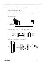
The GOT can be connected to the MELSEC A Series via a computer link unit shown below.
•
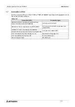
Applicable PLC and computer link unit
< A Series >
AJ71UC24, A1SJ71UC24-R2/R4/PRF, A1SJ71C24-R2/R4/PRF, A1SCPUC24-R2,
A2CCPUC24 (PRF)
System configuration
•
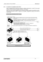
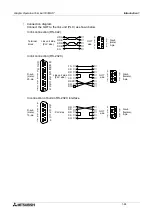
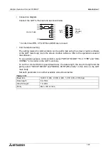
Connect the GOT to the computer link unit (PLC) as shown below.
In communication via RS-422
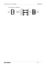
In communication via RS-232C
(Connection cable F2-232CAB is also available.)
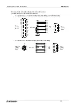
Refer to the figure on the right
for connection diagram.
To computer link unit
Programming
connector is not
used.
RS422
RS232C
Terminal
block
Computer link
unit side
(PLC side)
GOT
side
D-sub
(male),
9-pin
5
4
3
2
1
9
8
7
6
➀
➅
➆
➄
➁
RDA
RDB
SDB
SG
SDA
D-sub,
25-pin
➀
➁
➂
➇
➅
➄
FG
SD
RD
RS
CS
DSR
SG
CD
➃
DTR
➆
13
12
11
10
9
8
7
6
5
4
3
2
1
25
24
23
22
21
20
19
18
17
16
15
14
Computer link
unit side
(PLC side)
GOT
side
D-sub
(female),
9-pin
1
2
3
4
5
6
7
8
9
➀
➁
➂
➄
➅
➆
➃
➇
20
Summary of Contents for F930GOT-BWD-E
Page 1: ...USER S MANUAL F930GOT BWD E ...
Page 4: ...Graphic Operation Terminal F930GOT ii ...
Page 6: ...Graphic Operation Terminal F930GOT iv ...
Page 14: ...vi ...
Page 60: ...Graphic Operation Terminal F930GOT Start up 2 2 10 MEMO ...
Page 68: ...Graphic Operation Terminal F930GOT Screen Mode 3 3 8 MEMO ...
Page 120: ...Graphic Operation Terminal F930GOT Creation of Display Screens 8 8 30 ...
Page 200: ...Graphic Operation Terminal F930GOT Changeover of Display Screen FX PCS DU WIN E 10 10 18 ...
Page 272: ...Graphic Operation Terminal F930GOT Additional Functions in V 2 00 or later 13 13 24 MEMO ...


