5
.
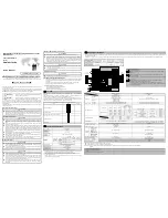
Part Names and Installation Method
【
Installation with the Base Adapter
】
MELSEC-L Series
Module
Mounting bracket
(supplied with
Conversion Adapter)
Mounting bracket fixing screw M3.5
×
6
(supplied with Conversion Adapter)
MELSEC-AnS Series
terminal block
Terminal block cover
(supplied with Conversion Adapter)
4
2
3
5
6
Conversion
Adapter
MELSEC-AnS Series terminal block installation screw (M4)
Conversion adapter installation screw M3
×
25
Precaution
Base Adapter
1
MELSEC-L Series
System
(
DIN rail portion
)
【
Installation with the DIN rail
】
4
2
3
5
6
DIN rail
1
Precaution
MELSEC-L Series
Module
Mounting bracket
(supplied with
Conversion Adapter)
Mounting bracket fixing screw M3.5
×
6
(supplied with Conversion Adapter)
MELSEC-AnS Series
terminal block
Terminal block cover
(supplied with Conversion Adapter)
Conversion
Adapter
MELSEC-AnS Series terminal block installation screw (M4)
Conversion adapter installation screw M3
×
25
MELSEC-L Series
System
5.1 Installation Method
Installation with the Base Adapter
Installation with the DIN rail
Remove the existing MELSEC-AnS
Series base unit, and install the base
adapter ERNT-ASLB
.
For how to install the base adapter,
refer to the base adapter manual.
Install the DIN rail on the control panel.
For how to install the DIN rail, refer to the user's
manual of the MELSEC-L CPU module.
Remove the terminal block attached with the MELSEC-L Series module after loosening the
terminal block installation screw (1 place).
The MELSEC-L series terminal block is not used.
Terminal block installation screw
Terminal block
Open the terminal cover and loosen
the terminal block installation screw.
Press the terminal block fixing holes until
the lower part of the terminal block is
disengaged from the module, and then
remove the terminal block.
Terminal block
fixing holes
1
2
Terminal block
cover
Secure the mounting bracket to the MELSEC-L Series module using the mounting bracket
fixing screws (M3.5 × 6). (1 place)
Serial number
display
Mounting bracket
Mounting bracket fixing screw
M3.5
×
6
Position the mounting bracket to the
serial number display area at the bottom
of the MELSEC-L Series module.
Tighten the Mounting bracket
fixing screw (M3.5
×
6).
1
2
(bottom)
Install the Conversion Adapter to the MELSEC-L Series module, and secure it using the
Conversion Adapter installation screws (M3 × 25). (1 place)
Conversion Adapter installation
screw M3
×
25
Fully insert the projections on the
top of the Conversion adapter into
the terminal block fixing holes.
Press the Conversion adapter
until it snaps into place.
Tighten the Conversion
Adapter installation screw
(M3
×
25).
projections
Terminal block
fixing holes
1
2
3
Precaution
Before tightening the installation screws, check that the Conversion Adapter has been
securely installed on the MELSEC-L Series module. Tightening the screws in floating-off
state or tilting state will damage the Conversion Adapter installation screws and the
mounting bracket.
Install the MELSEC-L Series system to the base adapter (DIN rail portion) or the DIN rail.
Secure the MELSEC-AnS Series terminal block to the Conversion Adapter with the supplied
MELSEC-AnS Series terminal block installation screw (M4). (2 places, top and bottom.)
Remove the terminal block cover from the MELSEC-AnS Series terminal block and fit the
terminal block cover supplied with the Conversion Adaptor in place.
5.2 Tightening Torque
Tighten the installation screws to the specified torque below. An inappropriate tightening torque could
cause the product to fall or result in a short circuit, product failure or malfunction.
Screw Location
Tightening Torque Range
Mounting bracket fixing screw (M3.5×6)
0.68 to 0.92N
・
m
Conversion Adapter installation screw (M3×25)
0.43 to 0.57N
・
m
MELSEC-AnS Series terminal block installation screw (M4 screw)
0.78 to 1.18N
・
m
6
.
External Dimensions
1
0
2
3
1
.5
28
Terminal block
cover
Mounting bracket
Unit
:
mm
Conversion adapter
Duplication Prohibited
This manual may not be reproduced in any form, in part or in whole, without written permission from
Mitsubishi Electric Engineering Company Limited.
©2014 MITSUBISHI ELECTRIC ENGINEERING COMPANY LIMITED
ALL RIGHTS RESERVED
MELSEC is a registered trademark of Mitsubishi Electric Corporation.
4
.
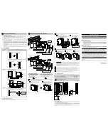
Mounting and Installation
4.1 Handling Precautions
(1) Before attempting to install the Unit or carry out the necessary wiring, make certain that the
external power supply, used in the system, is shut off on all three phases. Failure to do so may
result in electric shock or damage to the product.
(2) Do not touch live terminals. There is a danger of electric shock or malfunction.
(3) Do not modify the Conversion Adapter or take it apart. Doing so will cause failure, malfunction,
personal injury, or fire.
(4) Do not touch the energized part of the Conversion Adapter directly. Contact will cause
malfunction or failure in the system.
(5) Fasten the Conversion Adapter and the Mounting bracket securely with retaining screws, and
tighten the screws by applying torque within specified limits. Loose screws can lead to the
dropping of the Conversion Adapter, or Mounting bracket, possibly causing breakage thereof.
Excessive tightness of the screws can lead to breakage of the screws, Converter Adaptor,
Mounting bracket, or MELSEC-L Series Module, possibly causing the dropping, shorting, and
malfunction thereof.
(6) Use care to prevent foreign materials including cuttings and wiring debris from entering the
Conversion Adapter or the MELSEC-L Series Module. These will be cause for fire, failure or
malfunction.
(7) Do not drop the Conversion Adapter and Mounting Bracket or do not give a strong impact to it.
This will cause damage.
4.2 Use Precautions
Item
Use Precautions
Width dimension
of module
Because the module is reduced in width dimension (34.5mm
→
28.5mm) and
thus in area available for wiring, check dimensional data before installing the
module.
34.5mm
28.5mm
<MELSEC-AnS Series>
<MELSEC-L Series>
The wiring may interfere with the adjacent module. Use of the Mitsubishi
LG69 space module is recommended.
34.5mm
28.5mm
<MELSEC-AnS Series>
<MELSEC-L Series>
16.5mm
Space
Module
LG69
45mm
Depth and Height
dimension
Installation with the Base Adapter
Because the module is increased in depth dimension, check dimensional
data before installing the module.
110mm
161.3mm
MELSEC-AnS
Conversin
Adapter
Base Adapter
51.3mmUP
MELSEC-L
Installation with the DIN rail
Because the module is increased in depth and height dimension, check
dimensional data before installing the module.
106mm
144.5mm
38.5mmUP
5.2mmUP
7
0
.2
m
m
6
5
m
m
4mm
MELSEC-AnS
MELSEC-L
Conversin
Adapter
Terminal block
cover
The terminal block cover for MELSEC-AnS Series is bigger than the width of
the MELSEC-L Series Module. Therefore, it is necessary to replace it with
the terminal block cover supplied with the converter adapter.
34.5mm
28.5mm
<MELSEC-AnS Series>
<MELSEC-L Series>
Terminal block cover for
the MELSEC-AnS Series
Replace the terminal
block cover with the
one supplied with the
Conversion Adapter.
4.3 Installation Environment
The installation environment is the same as MELSEC-L series CPU Module to use. Refer to the user's
manual of the MELSEC-L Series CPU Module to be used.
Product Warranty Details
Please confirm the following product warranty details prior to product use.
Gratis Warranty Terms and Gratis Warranty Range
If any fault or defect (hereinafter referred to as “Failure”) attributable to Mitsubishi Electric Engineering
Company Limited (hereinafter referred to as “MEE”) should occur within the gratis warranty period,
MEE shall repair the product free of charge via the distributor from whom you made your purchase.
Gratis Warranty Period
The gratis warranty period of this product shall be one (1) year from the date of purchase or
delivery to the designated place.
Note that after manufacture and shipment from MEE, the maximum distribution period shall be
six (6) months, and the gratis warranty period after manufacturing shall be limited to eighteen
(18) months.
In addition, the gratis warranty period for repaired products shall not exceed the gratis warranty
period established prior to repair.
Gratis Warranty Range
The gratis warranty range shall be limited to normal use based on the usage conditions, methods
and environment, etc., defined by the terms and precautions, etc., given in the instruction
manual, user’s manual and caution labels on the product.
Warranty Period after Discontinuation of Production
(1) MEE shall offer product repair services (fee applied) for seven (7) years after production of the
product has been discontinued. Discontinuation of production shall be reported via distributors.
(2) Product supply (including spare parts) is not possible after production has been discontinued.
Exclusion of Opportunity Loss and Secondary Loss from Warranty
Liability
Regardless of the gratis warranty period, MEE shall not be liable for compensation for damages
arising from causes not attributable to MEE, opportunity losses or lost profits incurred by the user due
to Failures of MEE products, damages or secondary damages arising from special circumstances,
whether foreseen or unforeseen by MEE, compensation for accidents, compensation for damages to
products other than MEE products, or compensation for other work carried out by the user.
Changes in Product Specifications
The specifications given in the catalogs, manuals and technical documents are subject to change
without notice.
This document is a new publication, effective April 2014. Specifications are subject to change without
notice.
Developed April 2014
50CM-D180172-A
1
2
3
4
5
6


