English-59
English
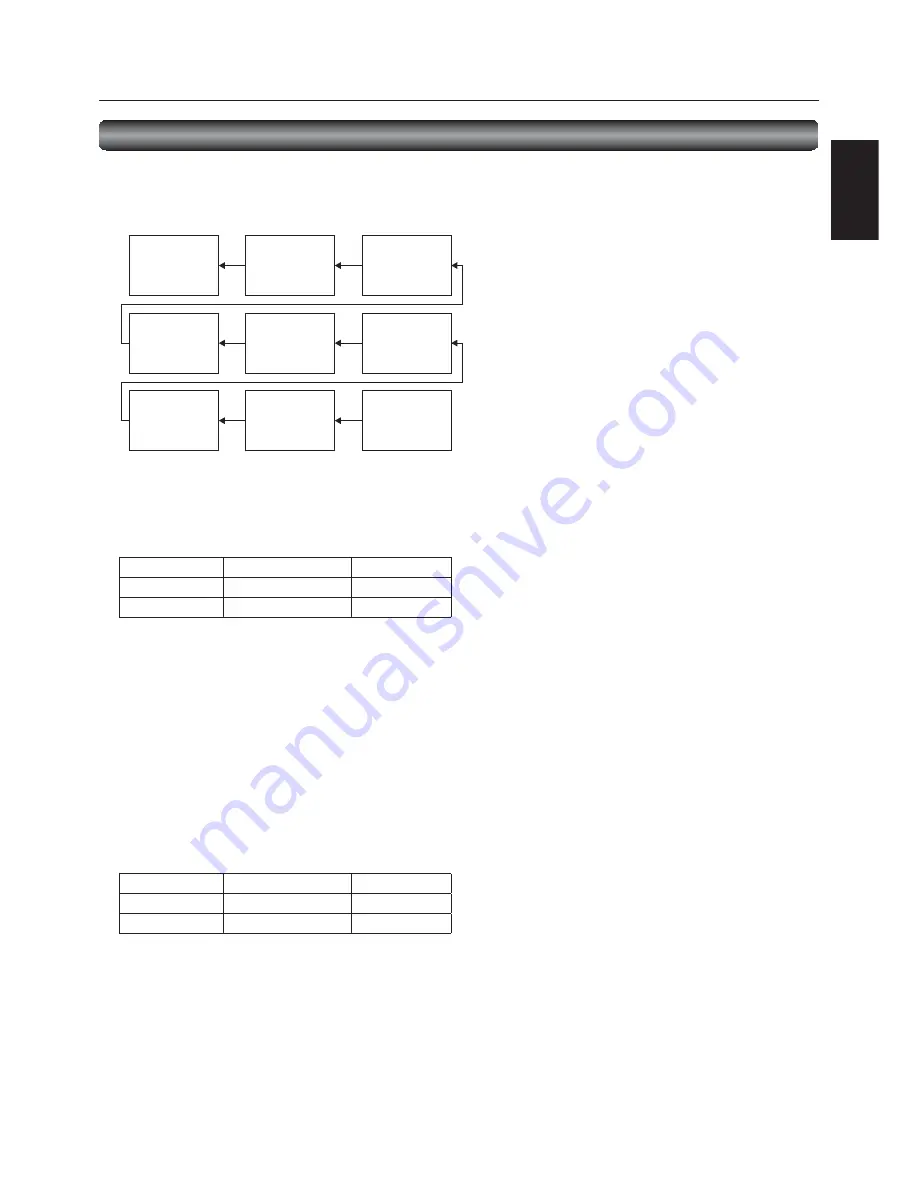
Master: Monitor confi gured as Master that detects the
outside light (Monitor ID is “1”.)
Slave:
Monitor controlled by the Master monitor (Monitor
ID is other than “1”.)
Monitor
ID = 9
(Slave)
Monitor
ID = 6
(Slave)
Monitor
ID = 3
(Slave)
Monitor
ID = 8
(Slave)
Monitor
ID = 5
(Slave)
Monitor
ID = 2
(Slave)
Monitor
ID = 7
(Slave)
Monitor
ID = 4
(Slave)
Monitor
ID = 1
(Master)
Other functions (continued)
Supplemental information of the auto brightness function
To control multiple monitors collectively
In such a case where the tiling function is used, you can control the auto brightness function by sharing the detection result of the
brightness sensor of a certain monitor among the connected monitors.
1. Multi-connect the monitors using RS-232C or CAT5 cables separately sold as shown by the example below.
2. Assign a monitor ID to each multi-connected MDT551S using MONITOR ID. (See page 54.)
Monitor ID is selectable from 1 to 26.
The monitor ID of the Master monitor should be “1” and those of the Slave monitors should be other than “1”.
You are recommended to assign IDs to the monitors consecutively from 1, 2, 3, and on.
3. Set AUTO BRIGHTNESS on the OSD screen (PICTURE) as follows.
AUTO BRIGHTNESS
CONTROL
Master monitor
LOCAL
PRIMARY
Slave monitors
REMOTE
SECONDARY
4. For connection with CAT5, set [RS485 TERMINATION] of the master monitor and the slave monitor at the end to ON. Set [RS485
TERMINATION] of the other slave monitors to OFF. See page 53.
To use a computer to control the monitors
When using a computer to control the monitors, you must prepare an application software program for control by yourself.
Brightness of all the monitors can be controlled centrally using a computer, if the customer create a control application to remotely
read the value from two brightness sensors of any monitor and distribute it to all monitors.
1. Connect the RS-232C IN connector of the Master monitor shown above and the RS-232C connector of the computer using an
RS-232C cable.
Using a CAT5 cable, connect the RS-232C connector of the computer to the CAT5 IN connector of the Master monitor via the
CAT5 Tx BOX.
The communication control function via LAN isn’t supported on the monitor alone, however, it is available when the monitor is
used with the computer.
2. Assign a monitor ID to each multi-connected MDT551S using MONITOR ID. (See step 2 on page 54.)
3. Set AUTO BRIGHTNESS on the OSD screen (PICTURE) as follows.
AUTO BRIGHTNESS
CONTROL
Master monitor
REMOTE
SECONDARY
Slave monitors
REMOTE
SECONDARY
4. For connection with CAT5, set [RS485 TERMINATION] of the master monitor and the slave monitors to ON. However, set [RS485
TERMINATION] of the slave monitor at the end to OFF. See page 53.
5. A control application made by the customer reads the value from two brightness sensors of any monitor and distributes it to all
monitors. For the specifi cations of the communication commands, contact your dealer.
NOTE:
When using CAT5 for control only, you can connect up to 26 monitors. When using the video function together, you are
recommended to connect only 4 or less monitors due to the restrictions of the video function. See page 25.


