[
VIII
Disassembly Procedure ]
- 24 -
HWE07170
GB
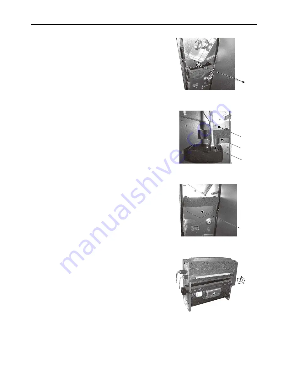
(2) Remove the magnet plate (G),(H),(I) of the both frame,re-
move the tube (J).
(3) Slide the drainpan in the direction of the arrow 1.
(G)
(H)
(J)
(I)
Page 1: ...Air Conditioners TECHNICAL SERVICE MANUAL Models PFFY P20VLRMM E PFFY P40VLRMM E PFFY P25VLRMM E PFFY P50VLRMM E PFFY P32VLRMM E PFFY P63VLRMM E For use with the R410A 2007 ...
Page 2: ...ak age electric shock or fire Properly install the unit on a surface that can withstand its weight Unit installed on an unstable surface may fall and cause in jury Only use specified cables Securely connect each cable so that the terminals do not carry the weight of the cable Improperly connected cables may produce heat and start a fire Take appropriate safety measures against wind gusts and earth...
Page 3: ...s made of phosphorus deox idized copper Keep the inner and outer surfaces of the pipes clean and free of such contaminants as sulfur oxides dust dirt shaving particles oil and moisture Contaminants in the refrigerant piping may cause the refrig erator oil to deteriorate Store the piping materials indoors and keep both ends of the pipes sealed until immediately before brazing Keep el bows and other...
Page 4: ...gram 8 VI Refrigerant System Diagram 1 Refrigerant system diagram 10 VII Troubleshooting 1 Troubleshooting 11 1 Check methods 11 2 DC fan motor fan motor indoor control board 15 3 Address switch setting 16 4 Voltage test points on the control board 17 5 Dipswitch setting Factory setting 18 VIII Disassembly Procedure 1 Disassembly Procedure 21 1 Control box 21 2 Thermistor Intake air 22 3 Drainpan ...
Page 5: ...HWE07170 GB ...
Page 6: ...E07170 GB I Features 1 Features Model Cooling capacity Heating capacity kW PFFY P20VLRMM E 2 2 2 5 PFFY P25VLRMM E 2 8 3 2 PFFY P32VLRMM E 3 6 4 0 PFFY P40VLRMM E 4 5 5 0 PFFY P50VLRMM E 5 6 6 3 PFFY P63VLRMM E 7 1 8 0 ...
Page 7: ... temperature The thermistor at the lower right hand section of the remote controller must be free from obstructions to ensure accurate mea surement of room temperature A Air 1 Set Temperature Button 7 Vane Control Button 2 Timer Menu Button 8 Ventilation Button Monitor Set Button Operation Button 3 Mode Button 9 Check Clear Button Back Button 10 Test Run Button 4 Timer On Off Button 11 Filter Butt...
Page 8: ... time I Louver swing B Centralized control indicator J Ventilation C Timer OFF indicator K Filter sign D Timer mode L Sensor position E Operation mode display COOL DRY AUTO FAN HEAT M Room temperature F Function Lock indicator N Vane setting G Preset temperature O Fan speed H Power indicator ...
Page 9: ...Y P32VLRMM E Power supply Voltage V 220 240 Frequency Hz 50 60 Cooling capacity 1 kW 2 2 2 8 3 6 Heating capacity 1 kW 2 5 3 2 4 0 Power consumption Cooling kW 0 04 0 04 0 04 0 04 0 04 0 04 Heating kW 0 04 0 04 0 04 0 04 0 04 0 04 Current consumption Cooling A 0 34 0 33 0 34 0 33 0 38 0 37 Heating A 0 34 0 33 0 34 0 33 0 38 0 37 External finish Munsel No Galvanized steel plate Dimensions Height mm...
Page 10: ...ge V 220 240 Frequency Hz 50 60 Cooling capacity 1 kW 4 5 5 6 7 1 Heating capacity 1 kW 5 0 6 3 8 0 Power consumption Cooling kW 0 05 0 05 0 05 0 05 0 07 0 07 Heating kW 0 05 0 05 0 05 0 05 0 07 0 07 Current consumption Cooling A 0 43 0 42 0 48 0 47 0 59 0 58 Heating A 0 43 0 42 0 48 0 47 0 59 0 58 External finish Munsel No Galvanized steel plate Dimensions Height mm 639 Width mm 1006 1246 Depth m...
Page 11: ...epping motor drive port diameter ø3 2 0 1400 pulse Power supply terminal block TB2 L N 330V 30A Transmission terminal block TB5 TB15 1 2 M1 M2 S 250V 20A Component Sym bol PFFY P40VLRMM E PFFY P50VLRMM E PFFY P63VLRMM E Room temperature thermistor TH21 Resistance 0 C 15k 10 C 9 6k 20 C 6 3k 25 C 5 4k 30 C 4 3k 40 C 3 0k Liquid pipe thermistor TH22 Resistance 0 C 15k 10 C 9 6k 20 C 6 3k 25 C 5 4k 3...
Page 12: ... Transmission wiring Control box Terminal bed Transmission Terminal bed Power souce Air outlet Air inlet Air filter Floor mounting hole pitch Floor mounting hole 2 12X16 Wall mounting hole pitch Wall mounting hole 2X2 12X16 Duct mounting hole 2XF 4 7 4 pcs attached Level adjusting screw 2 4 7 Duct mounting hole Refrigerant piping brazing connection gas O D 27mm End O D 20mm Drain hose accessory Su...
Page 13: ...1 s digit SW1 A B SWA 4 3 2 1 0 9 8 7 6 5 3 2 0 1 9 8 7 5 4 6 7 6 5 4 3 2 1 8 0 F E D C B A 9 Fan motor CN4F 1 2 TB15 TH21 t TH23 t TH22 t LEV M1 M2 S SHIELD TB5 Green Blue Red Red Red Red LED1 CN62 FUSE CN82 ZNR02 DSA LED2 DC310 340V Rectify circuit Blue CN60 POWER SUPPLY 220 230 240V 50 60Hz TO NEXT INDOOR UNIT CN3A CNMF PULL BOX CND CN2M SW2 SW4 SW3 CN90 BREAKER 16A CN42 CN81 CN32 CN27 CN20 CN4...
Page 14: ...r SW11 A B Switch For setting the 1 s digit in the address ZNR01 02 Varistor TH22 Thermistor liquid pipe SW12 A B Switch For setting the 10 s digit in the address DSA Arrester TH23 Thermistor gas pipe SW14 A B Switch connection No set ting L1 AC reactor Power factor im provement SW2 I B Switch capacity code setting SWA A B Switch static pressure set ting CN27 Connector Damper SW3 I B Switch functi...
Page 15: ...rmistor TH23 B Gas pipe C Liquid pipe D Brazed connections E Strainer 100 mesh F Linear expansion valve G Liquid pipe thermistor TH22 H Heat exchanger I Room temperature thermistor TH21 Capacity PFFY P20 25 32 40 50VLRMM E PFFY P63VLRMM E Gas pipe ø12 7 1 2 ø15 88 5 8 Liquid pipe ø6 35 1 4 ø9 52 3 8 H I F E E C G A D B ...
Page 16: ...nector and measure the resistance between terminals with a tester Refer to the next page for details Normal Abnormal 4 3k 9 6k Open or short Refer to the thermistor characteristic graph below Low temperature thermistor Room temperature thermistor TH21 Liquid pipe thermistor TH22 Gas pipe thermistor TH23 Thermistor R0 15 k 3 Multiplier of B 3480 k 2 0 C 15k 10 C 9 6k 20 C 6 3k 25 C 5 2k 30 C 4 3k 4...
Page 17: ...hanges in the following order When the valve closes 1 2 3 4 1 When the valve opens 4 3 2 1 4 When the valve position remains the same all output signals will be OFF If any output signal is missing or if the signal remains ON the motor vibrates and makes clicking noise A Brown F White B Red G Control board C Blue H Connection CN60 D Orange I Drive circuit E Yellow J Linear expansion valve Phase num...
Page 18: ...ia Remedy Circuit failure on the microcomputer Disconnect the connectors on the control board and connect LEDs to test the cir cuit as shown below Pulse signals are output for 10 seconds when the main power is turned on If there are LEDs that do not light up at all or remain lit after the pulses are turned off there is a problem with the driving circuit Replace the in door control board if driving...
Page 19: ...the LEV is fully closed while the unit is in the FAN mode If the valve is leaky liquid pipe thermistor reading will be lower than normal If it is significantly lower than the inlet temperature on the remote controller valve closure failure is suspected If the amount of leakage is insignificant replacement of LEV is unnec essary unless it is causing a problem Misconnections of connectors or con tac...
Page 20: ...sition thermistor signal Get the motor to make a full rotation or more and measure the voltage at the test point VFG same with the voltage between fan connector 7 and 4 Is the fan motor connector CNMF fully inserted Is the voltage within the normal range Replace the motor Are 0VDC and 15VDC displayed alternately Check the power supply Measure the voltage at the indoor control board 310 340VDC same...
Page 21: ...ller is used On site address setting is required for the indoor units to run 2 Address settings vary in different systems Refer to the section on address setting in the outdoor unit installation manual 3 Address is set with a combination of SW12 10 s digit and SW11 1 s digit To set the address to 3 set SW12 to 0 and SW11 to 3 To set the address to 25 set SW 12 to 2 and SW 11 to 5 A Indoor unit con...
Page 22: ...entralized control CN41 JAMA standard HA terminal A CN44 Thermistor liquid gas tempera ture CN20 Thermistor Inlet temperature CN3C Indoor outdoor transmission 0 24VDC CNMF Fan motor output 1 4 310 340 VDC 5 4 15 VDC 6 4 0 6 5 VDC 7 4 Stop 0 or 15 VDC Run 7 5 VDC 0 15 pulse 1 VFG Voltage on the side of PC941 and C25 Same with the voltage between 7 and 4 of CNMF VCC Voltage between the C25 pins 15 V...
Page 23: ...vailable 3 Filter life 2500 hr 100 hr 4 Outdoor air intake Enabled Disabled 5 Remote display Thermo ON signal Fan output 6 Humidifier operation During heating mode During heating operation 7 Fan speed Low Very low 8 Fan speed at heating Thermo OFF Preset fan speed Follows the setting of SW1 7 9 Auto restart after power failure Enabled Disabled 10 Power start stop Enabled Disabled Factory setting S...
Page 24: ... stop remote controller off There is no need to power cycle the unit 4 External static pressure 1 SWA SWC 1 Address board Note Changes that are made to the dipswitches SWA and SWC immediately become effective regardless of the unit s operation status RUN STOP or the remote controller status ON OFF Factory setting Factory setting A Option B Standard PFFY P20VLRMM E PFFY P25VLRMM E PFFY P32VLRMM E P...
Page 25: ... Address board Address settings must be made while the unit is stopped 6 Connection No setting 1 SW14 Rotary switch This switch is used when the unit connected to an R2 series of outdoor unit 1 Address board Note Changes to the dipswitches SW11 SW12 and SW14 must be made while the unit is stopped and the remote controller is OFF Factory setting Factory setting ...
Page 26: ...edure 21 HWE07170 GB VIII Disassembly Procedure 1 Disassembly Procedure 1 Control box Exercise caution when removing heavy parts 1 Removing the control box cover 1 Remove the fixing screws two on the cover A to re move it A ...
Page 27: ...Disassembly Procedure 22 HWE07170 GB 2 Thermistor Intake air Exercise caution when removing heavy parts 1 Removing the thermistor 1 Pull out the thermistor holder B and thermistor C under the control box B C ...
Page 28: ...inpan Exercise caution when removing heavy parts 1 Removing the casing ass y 1 Remove the fixing screws nine of the plate D and remove the plate 2 Remove the drainpan cover 3 Remove the drainpan 1 Remove the fixing screw of the both side frame D E F ...
Page 29: ... VIII Disassembly Procedure 24 HWE07170 GB 2 Remove the magnet plate G H I of the both frame re move the tube J 3 Slide the drainpan in the direction of the arrow 1 G H J I ...
Page 30: ...WE07170 GB 4 Thermistor Gas pipe Liquid pipe Exercise caution when removing heavy parts 1 Removing the thermistor 1 Remove the fixing screws three remove the cover K and L 2 Remove the thermistor gas M and thermistor liquid N K L M N ...
Page 31: ...rection of the arrow 2 4 Removing the fan motor 1 Remove the fixing screws three a on both sides of the fan casing O and turn the fan casing O in the upward di rection arrow 3 2 Remove the fan motor shaft fixing screw and remove the fan casing O and sirocco fan 3 Remove the fixing screws two b of the motor fix tures two and remove the motor Notice In case of the Model PFFY P32 63VLRMM E stick out ...
Page 32: ...r diffuser ass y 1 Remove the fixing screws eight of the air diffuser ass y P and remove it 3 Remove the cover1 2 with procedure 4 1 4 Removing the Heat exchanger 1 Remove the fixing screws four and remove the heat ex changer support 2 Remove the fixing screws two and remove the heat ex changer cover Q 3 Remove the heat exchanger moving from side to side P Q ...
Page 33: ...Nov 2007 HWE07170 Printed in Japan New publication effective Nov 2007 Specifications subject to change without notice ...