background image

GB

4

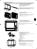
3.  Installing the indoor unit

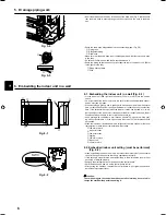
2) For right downward or left downward piping (Fig. 3-8)

(The following figure is a view of the bottom of the indoor unit from above.)

A

 When the unit is installed on the wall.

B

 When the unit is installed on the floor.

150

168

200

73

105

147

60

700

75

62

31

61

Fig. 3-8

60

19

60

19

60

60

Fig. 3-10

Fig. 3-9

2)

(mm)

4)

3)

3) For left piping (Fig. 3-9)
4) For right piping (Fig. 3-10)

3.4.3. Sealing the holes

Use putty or a caulking compound to seal the holes.

4. Refrigerant pipe

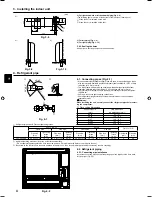
4.1. Connecting pipes (Fig. 4-1)

•  When commercially available copper pipes are used, wrap liquid and gas pipes 

with commercially available insulation materials (heat-resistant to 100°C or more, 
thickness of 12 mm or more).

•  The indoor parts of the drain pipe should be wrapped with polyethylene foam 

insulation materials (specific gravity of 0.03, thickness of 9 mm or more).

•  Apply thin layer of refrigerant oil to pipe and joint seating surface before tighten-

ing flare nut.

• Use two wrenches to tighten piping connections.
• Use refrigerant piping insulation provided to insulate indoor unit connections. 

Insulate carefully.

 Warning:

When installing the unit, securely connect the refrigerant pipes before start-
ing the compressor.

Copper pipe O.D.

(mm)

Flare dimensions

øA dimensions (mm)

ø6.35

8.7 - 9.1

ø9.52

12.8 - 13.2

ø12.7

16.2 - 16.6

ø15.88

19.3 - 19.7

ø19.05

23.6 - 24.0

Flare cutting dimensions

B

C

D

90

°

±0.5°

øA

R0.4 - R0.8

A

45°±2°

Fig. 4-1

B


Refrigerant pipe sizes & Flare nut tightening torque

R407C or R22

R410A

Flare nut O.D.

Liquid pipe

Gas pipe

Liquid pipe

Gas pipe

Pipe size

(mm)

Tightening

torque

(N·m)

Pipe size

(mm)

Tightening

torque

(N·m)

Pipe size

(mm)

Tightening

torque

(N·m)

Pipe size

(mm)

Tightening

torque

(N·m)

Liquid pipe

(mm)

Gas pipe

(mm)

P20/25/32/40

O.D. ø6.35 (1/4”)

14 - 18

O.D. ø12.7 (1/2”)

49 - 61

O.D. ø6.35 (1/4”)

14 - 18

O.D. ø12.7 (1/2”)

49 - 61

17

26

C


Apply refrigerating machine oil over the entire flare seat surface.

      * Do not apply refrigerating machine oil to the screw portions. (This will make the flare nuts more apt to loosen.)

D


Be certain to use the flare nuts those are attached to the main unit. (Use of commercially-available products may result in cracking.)

Fig. 4-2

4.2. Refrigerant piping

4.2.1. Connecting pipe installation

Install the connecting pipes so that the piping can move slightly to the front, back, 
left, and right. (Fig. 4-2)

Summary of Contents for CITY MULTI PFFY-P-VKM-E

Page 1: ...DE INSTALACIÓN Para un uso seguro y correcto lea detalladamente este manual de instalación antes de montar la unidad de aire acondicionado MANUAL DE INSTALAÇÃO Para uma utilização segura e correcta leia atentamente este manual e o manual de instalação da unidade exte rior antes de instalar o aparelho de ar condicionado PARA O INSTALADOR PER L INSTALLATORE PARA EL INSTALADOR VOOR DE INSTALLATEUR PO...

Page 2: ...rant should leak The cut face punched parts may cause injury by cut etc The installers are requested to wear protective equipment such as gloves etc When installing or relocating or servicing the outdoor unit use only the specified refrigerant R410A to charge the refrigerant lines Do not mix it with any other refrigerant and do not allow air to remain in the lines If air is mixed with the refriger...

Page 3: ...1 14 1 3 3 Indoor unit installation Fig 3 5 Hook the top of the indoor unit on the indoor unit mounting bracket Use the included wood screws and washer and fasten the indoor unit at 2 loca tions each at the top and the middle of the unit Note Install the indoor unit securely to the wall making sure that there is no gap between the unit and the wall 3 4 Making holes in the wall and floor 3 4 1 Maki...

Page 4: ...o insulate indoor unit connections Insulate carefully Warning When installing the unit securely connect the refrigerant pipes before start ing the compressor Copper pipe O D mm Flare dimensions øA dimensions mm ø6 35 8 7 9 1 ø9 52 12 8 13 2 ø12 7 16 2 16 6 ø15 88 19 3 19 7 ø19 05 23 6 24 0 A Flare cutting dimensions B C D 90 0 5 øA R 0 4 R 0 8 A 45 2 Fig 4 1 B Refrigerant pipe sizes Flare nut tigh...

Page 5: ...ghtly downward 1 100 or more so that the drain water flows easily Do not route the drain piping as shown in the examples mark with an X in the figure Fig 5 1 If the drain hose is too short refer to Fig 5 2 to extend the length of the hose If the indoor unit is installed in a high location such as a high rise apartment strong winds may cause the drain water to flow back through the drain hose and l...

Page 6: ...d etc to ad just the height of the indoor unit If the upper or lower air outlet is blocked the air conditioner will not be able to cool or warm the room well Use a grating with vertical bars etc that has at least 75 open area If the grat ing has horizontal bars or if the open area is less than 75 performance could be reduced When the indoor unit is embedded in a wall built in the time it takes for...

Page 7: ...bles refer to the outdoor unit installation manual Install a remote controller following the manual supplied with the remote control ler Connect the remote controller s transmission cable within 10 m using a 0 75 mm2 core cable If the distance is more than 10 m use a 1 25 mm2 junction cable 1 MA Remote controller Connect the connector for MA remote controller Non polarized 2 wire DC 9 to 13 V betw...

Page 8: ...arning Do not use the air conditioner if the insulation resistance is less than 1 0 M 8 2 Test run Using wired remote controller Fig 8 1 1 Turn on the power at least 12 hours before the test run 2 Press the TEST button twice TEST RUN liquid crystal display 3 Press the Mode selection button Make sure that wind is blown out 4 Press the Mode selection button and switch to the cooling or heating mode ...

Page 9: ...dress board SWC SWC Note Be sure to operate with the main power turned off Description of operation Operation Upper and lower air flow Room temperature and set temperature are dif ferent Upper air flow Room temperature is close to set temperature or thermo off Upper air flow only Upper and lower air flow Normal condition in heating Upper air flow During defrosting op eration start of opera tion th...

Page 10: ...ct at hand is based on the following EU regulations Low Voltage Directive 2006 95 EC Electromagnetic Compatibility Directive 2004 108 EC Machinery Directive 2006 42 EC Energy related Products Directive 2009 125 EC HEAD OFFICE TOKYO BLDG 2 7 3 MARUNOUCHI CHIYODA KU TOKYO 100 8310 JAPAN Authorized representative in EU MITSUBISHI EUROPE B V HARMAN HOUSE 1 GEORGE STREET UXBRIDE MIDDLE SEX UB8 1QQ U K ...

Reviews: