Mitsubishi Electric BH820 User Manual Download Page 16

English

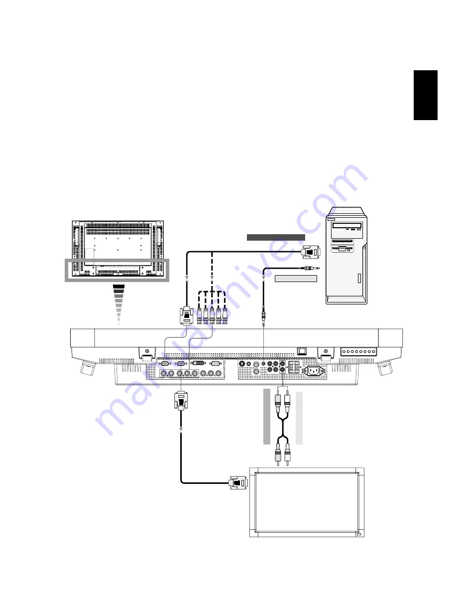
Connecting a Personal Computer

Connecting your computer to your LCD monitor will enable you to display your computer's screen image.
Some video cards may not display an image correctly.

Connect the LCD Monitor to a Personal Computer

•  To connect the RGB 2 IN connector (mini D-sub 15 pin) on the LCD monitor, use the supplied PC - Video RGB signal cable (mini 

D-sub 15 pin to mini D-sub 15 pin).

•  To connect the RGB 3 IN connector (BNC) on the LCD monitor, use a signal cable which is available separately (mini D-sub 

15 pin to BNC x 5).  Select RGB 3 from the INPUT button.

•  When connecting one or more LCD monitors, use the RGB OUT connector (mini D-sub 15 pin).
•  The AUDIO IN 1, 2 and 3 can be used for audio input. For connection, select AUDIO 1, 2 or 3 from the AUDIO INPUT button.
•  The AUDIO OUT jack outputs sound from the selected Audio input.

PC or IBM compatible

Mini D-sub 15 pin

To analog RGB output

Mini D-sub 15 pin

To audio output

LCD monitor (second monitor)

Mini D-sub 15 pin

BNC x 5

LCD monitor

To audio right output

To audio left output

1-16

Summary of Contents for BH820

Page 1: ...32 LCD Display Monitor USER S MANUAL 1 User s Manual 1 1 ...

Page 2: ...nnecting a DVD Player with component out English 17 Connecting to a Stereo Amplifier English 18 Basic Operation English 19 Power ON and OFF Modes English 19 Power Indicator English 20 Using Power Management English 20 Selecting a video source English 20 Picture Size English 20 Picture Mode English 20 Audio Source Switching English 20 Information OSD English 21 OSD On Screen Display Controls Englis...

Page 3: ...he supplied shielded video signal cable 15 pin mini D SUB to 15 pin mini D SUB 2 This equipment has been tested and found to comply with the limits for a Class B digital device pursuant to part 15 of the FCC Rules These limits are designed to provide reasonable protection against harmful interference in a residential installation This equipment generates uses and can radiate radio frequency energy...

Page 4: ...ce www eiae org For US only CAUTION Declaration Declaration of the Manufacturer We hereby certify that the color monitor LDT322V BH820 is in compliance with Council Directive 2006 95 EC EN 60950 1 Council Directive 2004 108 EC EN 55022 EN 61000 3 2 EN 61000 3 3 EN 55024 Declaration of the Manufacturer Note This symbol mark is for EU countries only This symbol mark is according to the directive 200...

Page 5: ...TOR DO NOT OPEN THE MONITOR There are no user ser viceable parts inside and opening or removing covers may expose you to dangerous shock hazards or other risks Refer all servicing to qualified service personnel Do not spill any liquids into the cabinet or use your monitor near water Do not insert objects of any kind into the cabinet slots as they may touch dangerous voltage points which can be har...

Page 6: ...al Speakers Stands Screw for Clamper M4 x 8 x 2 Video Signal Cable D SUB to D SUB Cable User s Manual Screw for Main switch cover 3 x 6 x 2 Main switch cover Cable Holder Clamper x 2 The supplied power cord varies depending on destination For EU For North America Power cord For all other case use a power cord that matches the AC voltage of the power outlet and has been approved by and complies wit...

Page 7: ...nction press both of and and hold down simultaneously for more than 3 seconds To resume back to user mode press both of and and hold simultaneously for three 3 seconds POWER button Switches the power on off See also page 19 MUTE button Switches the audio mute ON OFF INPUT button Acts as SET button with OSD menu Toggle switches between RGB1 RGB2 RGB3 DVD HD VIDEO S and VIDEO PLUS button Acts as but...

Page 8: ...ge 32 EXTERNAL SPEAKER TERMINAL To output the audio signal for external speakers from AUDIO 1 2 or 3 jack AC IN connector Connects with the supplied power cord RGB 1 IN DVI D To input digital RGB signals from a computer This connector does not support analog input RGB 2 IN mini D Sub 15 pin To input a analog RGB signals from a computer or other RGB equipment RGB 3 IN R G B H V BNC To input the ana...

Page 9: ...button Replaces to the main picture and sub pic ture Note The PIP and POP modes do not function when the screen size is CUSTOM or REAL STILL button ON OFF button To switch the still picture mode on off CAPTURE button Updates the still picture DISPLAY button To switch the information OSD on off See page 21 AUTO SETUP button To enter the auto setup menu See page 26 MENU button To switch the menu mod...

Page 10: ...ol Point the top of the remote control toward the LCD monitor s remote sensor during button operation Use the remote control within a distance of about 7 m 23 ft from the front of the LCD monitor s remote control sensor and at a horizontal and vertical angle of within 30 within a distance of about 3 m 10 ft CAUTION Important the remote control system may not function when direct sunlight or strong...

Page 11: ...stall the batteries 1 Press and slide to open the cover 2 Align the batteries according to the and indications inside the case 3 Replace the cover How to remove the batteries 1 Press and slide to open the cover 2 Remove the batteries CAUTION Incorrect use of batteries can result in leaks or bursting Be careful especially about the following points Place AAA batteries matching the and signs on each...

Page 12: ...1 Installing and removing the stands The stands are prepared as option How to install the stands 1 Please turn monitor off 2 After inserting stand in guide block fasten M6 x 16 screws on both sides of the monitor How to remove the stands 1 Spread the protective sheet on the flat surface such as a desk 2 Place monitor on the protective sheet 3 Remove screws with a screwdriver and place them in a sa...

Page 13: ...life of the LCD backlight Operational Environment Temperature shall be limited as shown below Operational Temperature 5 35 C 41 95 F Environment Humidity 20 80 without condensation Please orientate the monitor in the direction shown below Do not place monitor in landscape in any other manner Optional speakers SP 321V can not be attached when this LCD monitor is installed in portrait position How t...

Page 14: ...llar using rope commercially available strong enough to bear the weight of the monitor LDT322V approx 15 7 kg with the optional stands When you use screw hooks commercially available ring screw hooks not C shaped screw hooks with opening are recommended Before moving the LCD monitor the cord or chain should be removed Caution Install the monitor with metal brackets for wall or ceiling installation...

Page 15: ...ttached equipment and make connections Refer to the user manual included with each separate piece of equipment Wiring Diagram LCD monitor DVD player HD or laser disk player Equipment with digital interface Personal computer Personal computer LCD monitor second monitor VCR 1 15 ...

Page 16: ... connector BNC on the LCD monitor use a signal cable which is available separately mini D sub 15 pin to BNC x 5 Select RGB 3 from the INPUT button When connecting one or more LCD monitors use the RGB OUT connector mini D sub 15 pin The AUDIO IN 1 2 and 3 can be used for audio input For connection select AUDIO 1 2 or 3 from the AUDIO INPUT button The AUDIO OUT jack outputs sound from the selected A...

Page 17: ...DS signals conforming to DVI standards To maintain display quality use a cable with a quality prescribed by DVI standards See 29 page DVI MODE The AUDIO IN 1 2 and 3 can be used for audio input For connection select AUDIO 1 2 or 3 from the AUDIO INPUT button The signal input from DVI D connector cannot be output to the RGB OUT connector To audio output Equipment with a digital interface such as a ...

Page 18: ...nnector BNC on the LCD monitor use a separately available BNC connector cable You will need a BNC to RCA adapter to connect a DVD player with an RCA pin jack to the BNC connector cable not provided The AUDIO IN 2 and 3 both RCA can be used for audio input For connection select AUDIO 2 or AUDIO 3 from the AUDIO INPUT button DVD Player LCD monitor BNC x 3 RCA BNC to RCA adapter BNC x 3 To audio left...

Page 19: ...ctor RCA on the LCD monitor and the audio input on the amplifier Do not reverse the audio left and right jacks The AUDIO IN 2 and 3 both RCA can be used for audio input For connection select AUDIO2 or AUDIO3 from the AUDIO INPUT button The AUDIO OUT jack outputs sound from the selected Audio input LCD monitor VCR or CD player To composite Output In case of VCR To audio right output BNC BNC LCD mon...

Page 20: ...se two options 2 Pressing the power button NOTE Before pressing the power button be sure to turn on the Main Power button on the LCD monitor 3 Using the remote control NOTE Before operating the remote control be sure to turn on the Main Power Switch on the LCD monitor Power ON and OFF Modes The LCD monitor power indicator will turn green while powered on or red in off mode The monitor can be power...

Page 21: ...e To view a video source Use the input button to set VIDEO Use the COLOR SYSTEM menu to set AUTO NTSC PAL SECAM PAL60 4 43NTSC according to your video format Picture Size RGB 1 2 3 DVD HD VIDEO FULL NORMAL DYNAMIC CUSTOM REAL FULL NORMAL CUSTOM REAL Signal Type NORMAL DYNAMIC FULL 4 3 Squeeze NORMAL SIZE Recommended Size NORMAL Display by the inputed signal aspect ratio by PC signal or display in ...

Page 22: ...nput mode Audio input mode Picture Size mode DVD HD AUDIO 3 SIZE FULL VIDEO S VIDEO Video Input mode Input Signal Colour System mode Audio input mode Picture Size mode VIDEO S NTSC AUDIO 3 SIZE NORMAL PIP or POP Main RGB2 Sub VIDEO S Main picture Information Sub picture Information Main picture Information RGB2 1024 x 768 48kHz 60Hz AUDIO 1 VIDEO S NTSC SIZE FULL 1 22 ...

Page 23: ...ess UP or DOWN and PLUS or MINUS button to select function or control which you like Press INPUT button to decide Press INPUT button to decide Press EXIT button to exit Press UP or DOWN and PLUS or MINUS button to select function or control which you like Press SET button to decide Remote Control Control Panel OSD screen INPUT EXIT button EXIT button Press MENU or EXIT button to exit Press SET but...

Page 24: ... button to increase reduction level Press button to decrease reduction level TINT INPUT DVD HD VIDEO S VIDEO only Adjust the tint of the screen Press button the flesh tone color becomes greenish Press button the flesh tone color becomes purplish COLOR INPUT DVD HD VIDEO S VIDEO only Adjust the color of the screen Press button to increase color depth Press button to decrease color depth COLOR TEMPE...

Page 25: ...s the same as FULL size image when HDTV signal is input Selecting REAL image will be displayed 1 by 1 pixel CUSTOM ZOOM CUSTOM ZOOM will be selected when you select CUSTOM on the screen ZOOM mode ZOOM expands the horizontal and the vertical size simultaneously HZOOM expands the horizontal size only VZOOM expands the vertical size only H POSITION moves to the right with button moves to the left wit...

Page 26: ...tton to restore the factory preset Press EXIT button to cancel and then return to the previous menu AUDIO Main Menu PIP SIZE Selecting the size of picture inserted at the Picture in Picture PIP mode Large Middle and Small are available PIP AUDIO Selecting the sound source in PIP mode When selecting MAIN AUDIO you will get the sound for the main picture and when selecting PIP AUDIO you will get the...

Page 27: ...directions UP DOWN RIGHT LEFT periodically Need setting the time for movement Movement area is approximately 10mm from original position Please locate the important information such as text within 90 area of screen image See note 1 for this functions PIP and STILL will be disabled when MOTION is active COLOR SYSTEM INPUT VIDEO S VIDEO only Selecting the Color System depends on your input video for...

Page 28: ...change or warning message like as no signal or out of range A time between 1 to 10 seconds is available OFF TIMER To select OFF TIMER mode ON OFF In the OFF TIMER menu you can preset the monitor to automatically power down A time between 1 to 24 hours is available When the OFF TIMER is set the SCHEDULE see page 29 settings will be disabled OSD H POSITION Adjusts the horizontal position of the OSD ...

Page 29: ...erlace to Progressive converter function PROGRESSIVE Enable the IP function to convert interlace signal to progressive Normally use this setting INTERLACE Disable the IP function NOTE This mode is better suited for motion pictures but it increases chance of image retention FILM MODE INPUT DVD HD VIDEO S VIDEO only Selects Film mode function AUTO Enable the Film mode function This mode is better su...

Page 30: ...splayed on the screen POWER ON DELAY Adjusts the delay time from standby to power on mode POWER ON DELAY time is selectable from OFF 2sec 4sec 6sec 8sec 10sec 20sec 30sec 40sec and 50sec DATE AND TIME Adjusts the current date and time for internal clock You should set this function when you use SCHEDULE SCHEDULE Programs the monitor s working schedule Schedule the power on and power off with hour ...

Page 31: ...te control or use Power Management Function of monitor or use Schedule Function of monitor 3 Reducing the environmental temperature is effective for long life use When Protection board glass acryl is installed over the LCD surface enclosed into the box wall or stack the monitor please utilize the temperature sensors inside monitor To reduce the environmental temperature the monitor should be set L...

Page 32: ...ts 640 dots X 480 dots 320 dots X 240 dots POP SIZE PIP POP mode resolution Reference Press the PIP ON OFF buttons on the remote control to change between PIP and POP mode as shown in the diagram below NOTE 3 PIP and POP The following table shows the combination of signal inputs under which the PIP and POP modes function These modes do not function however when the screen size is CUSTOM or REAL 1 ...

Page 33: ...GTH PARITY BIT STOP BIT FLOW CONTROL RS 232C 9600 bps 8 bits NONE 1 bits NONE This LCD monitor uses RXD TXD and GND lines for RS 232C control For RS 232C cable the reverse type cable should be used 2 Control command diagram The command is structured by the address code function code data code and end code The length of the command is different for each function HEX ASCII Address code 30h 30h 0 0 F...

Page 34: ... 32h INPUT RGB 3 _r3 5Fh 72h 33h INPUT VIDEO _v1 5Fh 76h 31h INPUT DVD HD _v2 5Fh 76h 32h INPUT S VIDEO _v3 5Fh 76h 33h POWER OFF command should be operated over 1 minute after the power is turned on POWER ON command should be operated over 1 minute after the power is turned off S VIDEO is SEPARATE only 5 Read command Host computer sends the command without Data code to monitor After receiving thi...

Page 35: ...onsumption level when on but not in use saving two thirds of your monitor energy costs reducing emissions and lowering the air conditioning costs of the workplace Multiple Frequency Technology Automatically adjusts monitor to the display card s scanning frequency thus displaying the resolution required FullScan Capability Allows you to use the entire screen area in most resolutions significantly e...

Page 36: ...ing moving images and using a moving screen saver at regular intervals whenever the screen is idle or turning off the monitor when not in use Image is unstable unfocused or swimming is apparent Signal cable should be completely attached to the computer Use the OSD Image Adjust controls to focus and adjust display by increasing or decreasing the fine adjustment When the display mode is changed the ...

Page 37: ...ol is pointing at the monitor s remote sensor SCHEDULE OFF TIMER function is not working properly The SCHEDULE function will be disabled when the OFF TIMER is set If the OFF TIMER function is enable and the power to the LCD monitor is turned off if the power supply is interrupted unexpectedly then the OFF TIMER will be reset Stripe Noise Either light vertical or horizontal stripes may appear depen...

Page 38: ...ut Impedance 75 ohm BNC INPUT RCA PIN JACK L R INPUT x 2 STEREO Mini Jack INPUT x 1 9 Pin Mini D sub Analog RGB Video 0 7 Vp p with 75 ohm terminated Separate HV sync TTL level Pos Neg 15 Pin Mini D sub BNC OUTPUT x 1 Composite 1 0 Vp p with 75 ohm terminated RCA PIN JACK L R OUTPUT x 1 0 15 Vrms with 47k ohm terminated External Speaker Jack 7 W 7 W 8 ohm 640 x 480 at 60 Hz to 85 Hz 800 x 600 at 5...

Page 39: ...V I D E O S MINI DIN 4P Name GND GND Y Luminance C Chroma Pin No 1 2 3 4 3 Digital RGB input DVI D R G B 1 1 2 3 4 5 6 7 8 9 10 11 12 13 14 15 16 17 18 19 20 21 22 23 24 Pin Assignment of DVI connector TX2 TX2 Shield TX2 TX4 NC NC DDC Serial Clock DDC Serial Data NC TX1 TX1 Shield TX2 TX3 NC NC 5V power Ground Hot plug detect TX0 TX0 Shield TX2 TX5 NC NC Shield TXC TXC TXC 1 17 24 16 8 9 DVI D 4 R...

Reviews: