α
2 Simple Application Controllers
Function Blocks 6
6 - 52
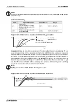
Setup of the Pulse Width Modulation Function Block directly from the
α
2
Series Controller
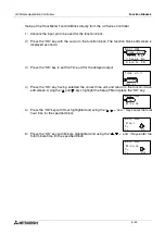
1 ) Allocate the input pin to be used for the function block.
2 ) Press the “OK” key with the cursor in the function block. The function block edit screen is
displayed as shown.
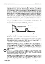
3 ) Press the “OK” Key and enter the function block settings using the “Up and Down” keys.
4 ) Press the “OK” key with Period highlighted and the user can enter a T and t value using the
“ , , + and -” keys.
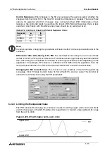
5 ) Press the “OK” key to return to the function block settings screen. Highlight the Duty option
using the “ 0 and ” keys. The Duty can be entered by pressing the “OK” key. A Directset
value, Analog In or FB value can be entered.
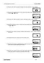
Press the “ESC” key until the user returns to the function block diagram.
B 0 0 1 : P
W
C h a n g e N o
D e l e t e
F B
M
S e t u p
F B
P e r i o d
D u t y
B 0 0 1 : PWM
P e r i
T =
s
t =
s
o d
0
0
.
.
1
0
B 0 0 1 : P
W
M
D i r e c t S e t
A n a l o g
I n
F B V a l u e
B 0 0 1 : P
W
M

