13-219
13-219
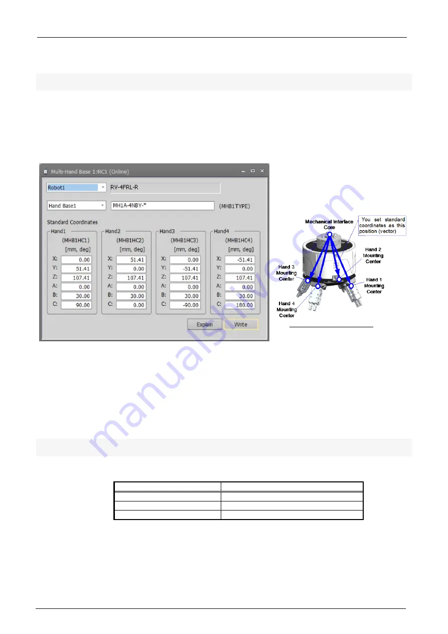
13.3.3.2. Multi-hand base parameter
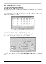
You can set multi-hand base model name and
standard coordinate values for each hand.
When connecting robot and the robot
controller supports multi-hand function, items related to multi hand are
displayed in the project tree.
For robots and robot controllers that can use multi hand base, please see”
Table 13-3 The controller that can
use parameters about multi-hand tool”
.
Parameter settings are used while connected to the robot controller.
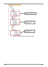
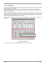
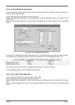
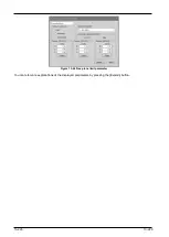
From the project tree, you double-click [Movement Parameter] -> [Hand] -> [Multi-Hand Base] under [Parameter]
item to be edited.
After changing the parameter value, you click the [Write] button to write the parameters to the robot controller.
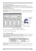
Figure 13-16
Multi-hand base parameter
You can refer to the explanation of the displayed parameter with the [Explain] button.
This parameter cannot be set by offline editing.
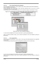
13.3.3.3. Multi-hand tool parameter
You can set multi-hand tool selections and
the offset value of each hand with respect to the selected hand base.
The multi-hand tool can be connected to robot with remote I/O or parallel I/O.
When connecting robot and the robot
controller supports multi-hand function, items related to multi hand are
displayed in the project tree.
The robots and robot controllers that can use the multi-hand tool are as follows.
Table 13-3 The controller that can use parameters about multi-hand tool
Robot controller
Software version of robot controller
CR800-D/CR800-R/CR800-Q
All versions
CR750-D/CRnD-700
Ver.S2a or later
CR750-Q/CRnQ-700
Ver.R2a or later
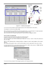
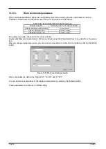
Parameter settings are used while connected to the robot controller.
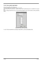
From the project tree, you double-click [Movement Parameter] -> [Hand] -> [Multi-Hand Tool] under [Parameter]
item to be edited.
After changing the parameter value, you click the [Write] button to write the parameters to the robot controller.
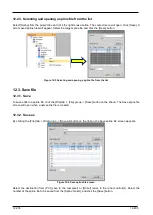
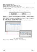
Set standard coordinates
Summary of Contents for 3F-14C-WINE
Page 84: ...8 84 8 84 Figure 8 21 Parameter transfer procedure 1 2 2 ...
Page 393: ...18 393 18 393 Figure 18 1 Starting the Oscillograph ...
Page 413: ...18 413 18 413 Figure 18 24 Output to Robot program Selection ...
Page 464: ...18 464 18 464 Figure 18 72 Starting the Tool automatic calculation ...
Page 545: ...21 545 21 545 Figure 21 55 Hide display of user mechanism ...
Page 624: ...24 624 24 624 Figure 24 4 Document output example ...

