


25
ELECTRIC WIRE ROPE HOIST
XM SERIES
3.9.5
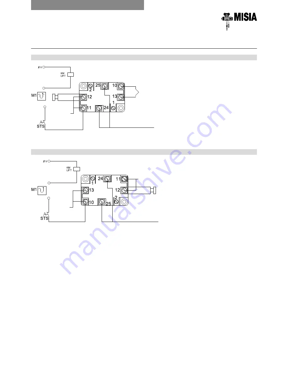
END LIMIT SWITCH
WIRING CONNECTIONS
EXTERNAL END LIMIT SWITCH
END LIMIT SWITCH INSIDE THE MOTOR TERMINAL BOARD
LIFTING/DESCENT
EMERGENCY CONTACT
LIFTING PROBES
*(lifting contactor)
LIFTING
DESCENT
LIFTING/DESCENT
EMERGENCY CONTACT
LIFTING PROBES
LIFTING PROBES
LIFTING
DESCENT
3. INSTALLATION INSTRUCTIONS
Summary of Contents for XM SERIES
Page 2: ......
Page 71: ...71 Manual for installation operation and maintenance of the wire rope hoists XM Series NOTE ...
Page 72: ...72 Manual for installation operation and maintenance of the wire rope hoists XM Series NOTE ...
Page 73: ...73 Manual for installation operation and maintenance of the wire rope hoists XM Series NOTE ...
Page 74: ...74 Manual for installation operation and maintenance of the wire rope hoists XM Series NOTE ...
Page 75: ......


