background image

14

SURFACE MAINTENANCE:

Clean periodically with hot soapy water and clean cotton cloth. Do not use corrosive or abrasive detergent, 
or steel wool/scouring pads which will scratch and damage surface.  Do not use products containing chlorine 
bleach or orange cleaners.

For heavier soil use liquid degreaser.

After cleaning, you may use non-abrasive stainless steel polish/ cleaners, to polish and buff out the stainless 

OXVWHUDQGJUDLQ$OZD\VVFUXEOLJKWO\XVLQJDPLFUR¿EHURUFOHDQFRWWRQFORWKDQGZLWKJUDLQ

6WDLQOHVV6WHHO%DIÀH)LOWHUV

7KHVWDLQOHVVVWHHOEDIÀH¿OWHUVDUHLQWHQGHGWRWUDSUHVLGXHDQGJUHDVHIURPFRRNLQJ$OWKRXJKWKH¿OWHUV

should never need replacing, they are required to be cleaned every 30 days or more often depending on 
cooking habits.

)LOWHUVPD\EHSODFHGLQGLVKZDVKHUDWORZKHDWRUVRDNHGLQKRWVRDS\ZDWHU'U\¿OWHUVDQGUHLQVWDOOEHIRUH

using hood.

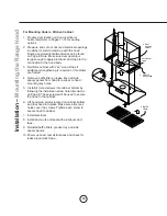
5HPRYLQJ%DIÀH)LOWHUV)LJ

 3XOO¿OWHUWRZDUGIURQWRIUDQJHKRRGXVLQJKDQGOHV
 3LYRWUHDURI¿OWHUGRZQZDUG
 5HPRYH¿OWHUE\SXOOLQJDZD\IURPKRRG

1

2

3

Maintenance – 

Cleaning and Filter Removal

Fig.01

Cleaning the Grease Tray

The grease tray is intended to catch residue and grease that may drip 

IURPWKHEDIÀH¿OWHUV7KHJUHDVHWUD\VKRXOGEHFOHDQHGZKHQEDIÀH
¿OWHUVDUHFOHDQHG&OHDQWKHJUHDVHWUD\E\VRDNLQJLQKRWVRDS\

water and gently scrubing any residue off with a soft terry cloth. Dry 
grease tray and re-install before using hood. 

Removing the Grease Tray

Grease tray has a hooked lip that attaches to bottom panel top edge. 

Remove grease tray by:

1. Pull up on tray to release from bottom panel. 

2. Pull tray out of liner body.  

Summary of Contents for MH70330AS

Page 1: ...2015 OCT MH70330AS MH70336AS MODEL Installation Use and Care Guide READ AND SAVE THESE INSTRUCTIONS ...

Page 2: ......

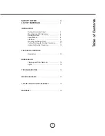
Page 3: ...ns 7 6SHFL FDWLRQV 8 Electrical 9 Mounting the Range Hood 10 Vertical Rectangular Ducting Conversion 11 Horizontal Ducting Conversion 12 FEATURES CONTROLS Rotary Dial 13 MAINTENANCE Cleaning and Filter Removal 14 Lights 15 TROUBLESHOOTING 16 WIRING DIAGRAMS 17 LIST OF PARTS AND ACCESSORIES 18 WARRANTY 18 Table of Contents ...

Page 4: ...ensils appropriate for the type of and amount of food being prepared WARNING TO REDUCE THE RISK OF INJURY TO PERSONS IN THE EVENT OF A RANGE TOP FIRE OBSERVE THE FOLLOWING D 6027 5 0 6 ZLWK D FORVH WWLQJ OLG FRRNLH VKHHW RU PHWDO WUD WKHQ WXUQ RII WKH EXUQHU 5 8 72 35 9 17 8516 I WKH ÀDPHV GR QRW JR RXW LPPHGLDWHO 9 8 7 1 7 5 3 570 17 b NEVER PICK UP A FLAMING PAN You may be burned c DO NOT USE WA...

Page 5: ...trical installation is adequate and in conformance with National Electrical Code ANSI NFPA 70 latest edition or CSA standards C22 1 94 Canadian Electrical Code Part 1 and C22 2 No 0 M91 latest edition and all local codes and ordinances I FRGHV SHUPLW DQG D VHSDUDWH JURXQG ZLUH LV XVHG LW LV UHFRPPHQGHG WKDW D TXDOL HG HOHFWULFLDQ GHWHUPLQH WKDW WKH ground path is adequate Do not ground to a gas pi...

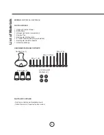
Page 6: ...idue Tray 1 Rectangular starting collar URXQG WUDQVLWLRQ DGDSWRU SUH LQVWDOOHG 1 Rectangular transition adaptor 1 Hardware package HARDWARE PACKAGE CONTENTS PARTS NOT SUPPLIED Ducting conduit and all installation tools DEOH FRQQHFWRU if required by local codes Suction Cup 1 M6 x 1 4 M6 x 1 1 2 4 M6 x 2 4 Wire Caps 3 4 ø12 OD ø5 ID Washers ...

Page 7: ...10 Round roof cap 30 Ft x Ft Subtotal column 2 Subtotal column 1 Total ductwork Maximum Duct Length For satisfactory air movement the total duct length should not exceed 100 equivalent feet 6 roundto 3 1 4 x 10 rect transition 1 Ft x Ft 6 roundto 3 1 4 x 10 rect transition 900 elbow 16 Ft x Ft 7 roundto 3 1 4 x 10 rect transition 8 Ft x Ft 7 roundto 3 1 4 x 10 rect transition 900 elbow 23 Ft x Ft ...

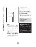
Page 8: ...gher than 32 It is important to install the hood at the proper mounting height Hoods mounted too low could UHVXOW LQ KHDW GDPDJH DQG UH KD DUG ZKLOH KRRGV mounted too high will be hard to reach and will ORVH LWV SHUIRUPDQFH DQG HI FLHQF If available also refer range manufacturer s height clearance requirements and recommended hood mounting height above range Vertical Ducting 6 round or 3 1 4 x10 m...

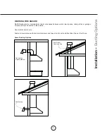
Page 9: ...g attics or garages All exhaust must be ducted to the outside Use metal ductwork only DVWHQ DOO FRQQHFWLRQV ZLWK VKHHW PHWDO VFUHZV DQG WDSH DOO MRLQWV ZLWK FHUWL HG 6LOYHU 7DSH RU XFW 7DSH Some Ducting Options Installation Ducting Options Side wall cap w gravity damper Roof Pitch w Flashing Cap Rear Ducting ...

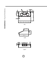
Page 10: ...8 Installation 6SHFL FDWLRQV top side back 1 7 8 4 10 5 8 5 7 8 4 2 5 8 2 22 1 2 29 15 16 30 35 15 16 36 12 8 22 1 2 3 9 13 16 3 1 8 2 5 8 1 3 8 ...

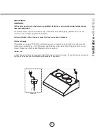
Page 11: ...ing local codes and ordinances Electrical Supply This appliance requires a 120V 60Hz electrical supply and connected to an individual properly grounded branch circuit protected by a 15 or 20 ampere circuit breaker or time delay fuse Wiring must be 2 wire w ground Please also refer Electrical Diagram labeled on product Cable Lock FDEOH ORFNLQJ FRQQHFWRU QRW VXSSOLHG PLJKW DOVR EH UHTXLUHG E ORFDO F...

Page 12: ...inets are framed 5HPRYH EDIÀH OWHUV JUHDVH WUD DQG VLGH spacer panels from hood for access to hood mounting key holes QVWDOO ZRRG VFUHZV LQWR FDELQHW ERWWRP E following the installation screw hole dimensions on Page 8 These screws will be used to secure the hood to the cabinet 6 Lift hood onto screws located on cabinet bottom DQG ORFN KRRG LQWR SODFH 0DNH VXUH DOO NH holes cover the screws TIghten...

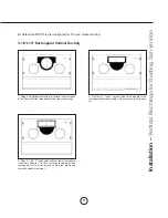
Page 13: ...QG YHUWLFDO WUDQVLWLRQ DGDSWHU IURP WRS RI KRRG ERG 5HSODFH URXQG YHUWLFDO WUDQVLWLRQ DGDSWHU ZLWK rectangular transition adapter Do not secure to hood body yet 3ODFH UHFWDQJXODU FROODU RQ WRS RI UHFWDQJXODU transition adapter Secure rectangular adapter and rectangular collar to hood body using the previously removed screws from step 1 3 1 4 x10 Rectangular Vertical Ducting ...

Page 14: ... secure using the screws that previously secured the rectangular cover plate 3 1 4 x10 Rectangular Horizontal Ducting 3ODFH UHFWDQJXODU FRYHU SODWH RYHU WKH rectangular opening on top of hood from step 4 Secure rectangular transition adapter and cover plate to hood body using the previously removed screws from step 1 3 Remove the two plastic air diverter blocks The blocks are located in the hood a...

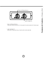
Page 15: ... Off Speed Selection 2 Lights Dim Bright Off 1 Blower On Off Speed Selection 2 Lights Dim Bright Off Rotate dial to change speed levels 1 for low speed 2 for medium speed and 3 for high speed Rotate dial to change light settings 1 for dim light and 2 for bright light ...

Page 16: ... every 30 days or more often depending on cooking habits LOWHUV PD EH SODFHG LQ GLVKZDVKHU DW ORZ KHDW RU VRDNHG LQ KRW VRDS ZDWHU U OWHUV DQG UH LQVWDOO EHIRUH using hood 5HPRYLQJ DIÀH LOWHUV LJ 3XOO OWHU WRZDUG IURQW RI UDQJH KRRG XVLQJ KDQGOHV 3LYRW UHDU RI OWHU GRZQZDUG 5HPRYH OWHU E SXOOLQJ DZD IURP KRRG 1 2 3 Maintenance Cleaning and Filter Removal Fig 01 Cleaning the Grease Tray The grease ...

Page 17: ...e by turning bulb counter clockwise Note Bulb does not unscrew it turns 60 degrees stops and falls out I EXOEV DUH GLI FXOW WR WXUQ GXH WR SURORQJHG XVH UPO DWWDFK D JODVV VXFWLRQ FXS DSSUR LPDWHO WKH GLDPHWHU RI the bulb or use a rubber latex glove and turn counter clockwise 5HSODFHPHQW EXOEV DUH DYDLODEOH DW VSHFLDOW OLJKWLQJ VWRUHV 3XUFKDVH W SH 05 8 KDORJHQ For part numbers please turn to page...

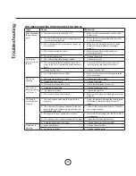
Page 18: ...wire is plugged into the molex connector The unit is vibrating 1 The motor is not secure in place 1 Tighten the motor in place 2 Damaged blower wheel 2 Change the blower 3 The hood is not secured in place 3 Check the installation of the hood The motor is working but the lights are not 1 Defective halogen bulb 1 Change the halogen bulb 2 The light bulb is loose 2 Tighten the light bulb 3 The wires ...

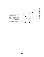
Page 19: ...17 Wiring Diagrams Model MH70330AS MH70336AS Voltage 120V 60Hz Power consumption Total Max 225W 2A Lamp Max 35Wx2 Fan Max 155W THERMALLY PROTECTED CIRCUIT DIAGRAM ...

Page 20: ...18 DESCRIPTION PART Replacement Parts LJKW XOE 05 8 HDFK DIÀH LOWHU HDFK To order parts please call us at 1 888 750 1698 List of Parts and Accessories ...

Page 21: ...u are also responsible for all labor costs associated with this warranty Limitations of Warranty OUR OBLIGATION TO REPAIR OR REPLACE AT OUR OPTION SHALL BE YOUR SOLE AND EXCLUSIVE REMEDY UNDER THIS WARRANTY WE SHALL NOT BE LIABLE FOR INCIDENTAL CONSE QUENTIAL OR SPECIAL DAMAGES ARISING OUT OF OR IN CONNECTION WITH THE USE OR PERFORMANCE OF THE PRODUCTS THE EXPRESS WARRANTIES IN THE PRECEDING SECTI...

Reviews: