MIRKA 000 RPM Service Instructions Manual Download Page 6

5

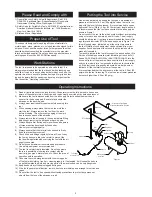
Closed Loop Pipe System

Sloped in the direction of air flow

Drain Leg

Ball Valve

To Tool Station

Filter

Drain Valve

Regulator

Lubricator

Ball

Valve

Ball Valve

Air Flow

Air Dryer

Air Compressor

and Tank

Air Hose

To Coupler

at or near Tool

 Please Read and Comply with

Putting the Tool into Service

Operating Instructions

Work Stations

Proper Use of Tool

Figure 1

1) General Industry Safety & Health Regulations, Part 1910, 

OSHA 2206, available from: Superintendent of Documents; 

Government Printing Office; Washington DC 20402

2) Safety Code for Portable Air Tools, ANSI B186.1 available from: 

American National Standards Institute, Inc.; 1430 Broadway; 

New York, New York 10018

3) State and Local Regulations.

This sander is designed for sanding all types of materials i.e. 

metals, wood, stone, plastics, etc. using abrasive designed for this 

purpose. Do not use this sander for any other purpose than that 

specified without consulting the manufacturer or the manufac

-

turer’s authorized supplier. Do not use back-up pads that have a 

working speed less than 8,000 RPM free speed..

The tool is intended to be operated as a hand held tool. It is 

always recommended that the tool be used when standing on a 

solid floor. It can be in any position but before any such use, the 

operator must be in a secure position having a firm grip and foot

-

ing and be aware that the sander can develop a torque reaction. 

See the section “Operating Instructions”.

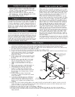
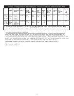
Use a clean lubricated air supply that will give a measured air 

pressure at the tool of 6.2 bar (90 psig) bar when the tool is run-

ning with the lever fully depressed. It is recommended to use an 

approved 10 mm (3/8 in.) x 8 m (25 ft) maximum length airline. It 

is recommended that the tool be connected to the air supply as 

shown in Figure 1.

Do not connect the tool to the airline system without incorporating 

an easy to reach and operate air shut off valve. The air supply 

should be lubricated. It is strongly recommended that an air filter, 

regulator and lubricator (FRL) be used as shown in Figure 1 as 

this will supply clean, lubricated air at the correct pressure to 

the tool. Details of such equipment can be obtained from your 

supplier. If such equipment is not used then the tool should be 

manually lubricated

To manually lubricate the tool, disconnect the airline and put 2 to 

3 drops of suitable pneumatic motor lubricating oil such as Fuji 

Kosan FK-20, Mobil ALMO 525 or Shell TORCULA® 32 into the 

hose end (inlet) of the machine. Reconnect tool to the air supply 

and run tool slowly for a few seconds to allow air to circulate the 

oil. If the tool is used frequently, lubricate it on a daily basis or 

lubricate it if the tool starts to slow or lose power.

It is recommended that the air pressure at the tool is 6.2 bar (90 

psig) while the tool is running. The tool can run at lower pressures 

but never higher than 6.2 bar (90 psig).

1)    Read all instructions before using this tool. All operators must be fully trained in its use and 

    aware of these safety rules. All service and repair must be carried out by trained personnel. 

2)    Make sure the tool is disconnected from the air supply. Select a suitable abrasive and 

    secure it to the back-up pad. Be careful and center the 

    abrasive on the back-up pad.

3)    Always wear required safety equipment when using this 

   tool.

4)    When sanding always place the tool on the work then  

  start the tool. Always remove the tool from the work 

    before stopping. This will prevent gouging of the work 

    due to excess speed of the abrasive.

5)    Always remove the air supply to the sander before fitting,  

  adjusting or removing the abrasive or back-up pad.

6)    Always adopt a firm footing and/or position and be aware  

  of torque reaction developed by the sander.

7)    Use only correct spare parts.

8)    Always ensure that the material to be sanded is firmly  

  fixed to prevent its movement.

9)    Check hose and fittings regularly for wear. Do not carry  

  the tool by its hose; always be careful to prevent the  

  tool from being started when carrying the tool with the air  

  supply connected. 

10)  Do not exceed maximum recommended air pressure. 

Use safety equipment as recommended.

11)  The tool is not electrically insulated. Do not use where 

there is a possibility of coming into contact with live 

electricity, gas pipes, water pipes, etc. Check the area of 

operation before operation.

12)  Take care to avoid entanglement with the moving parts 

of the tool with clothing, ties, hair, cleaning rags, etc. If entangled, it will cause the body to 

be pulled towards the work and moving parts of the machine and can be very dangerous.

13)  Keep hands clear of the spinning pad during use.

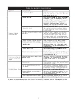
14)   If the tool appears to malfunction, remove from use immediately and arrange for service and  

 repair.

15)   Do not allow the tool to free speed without taking precautions to protect any persons or 


 objects from the loss of the abrasive or pad.

Summary of Contents for 000 RPM

Page 1: ...Operating Instructions English Operating Instructions 1 10 Fran ais Notice d utilisation 11 17 Espa ol Instrucciones de manejo 19 25 Random Orbital Sander MIRKA 32 mm 11 4 in...

Page 2: ...A0019 1 11 XPA0045 3 12 XPA0001 L 13 XPA0145 1 14 XPB0099 1 15 XPA0702 T 15 XPA2599 T 16 XPA0031 L 17 XPA0288 G 17 XPA0289 G 17 XPA0290 G 18 XPA0015 V 19 XPA0703 M 20 XPA1979 8 21 XPA0068 M 22 XPA0166...

Page 3: ...ING 1 20 MPA1979 INTERNAL MUFFLER 1 21 MPA0068 MUFFLER INSERT 1 22 MPA0166 MUFFLER HOUSING 1 23 MPA0009 VALVE SEAT 1 24 MPA0007 VALVE 1 25 MPA0014 VALVE SPRING 1 26 MPA0013 INLET BUSHING ASSEMBLY 1 27...

Page 4: ...ES A PART WAS DWG TITLE SET ITEM 1 DE ITEM 2 DE ITEM 3 DE ITEM 4 DE ITEM 5 DE RAG 03 04 B ITEM 8 X NOT ON MJW 11 26 C ITEMS 9 WERE NOT MCC 04 19 GENERIC S XPA P N TITLE DRWN BY DATE MATERIAL PROPRIETA...

Page 5: ...ective 2006 42 EC Place and date of issue Name Signature or equivalent marking of authorized person Warranty The warranty terms are as follows 12 months on KWH MIRKA air tools 3 months on tool parts r...

Page 6: ...s of suitable pneumatic motor lubricating oil such as Fuji Kosan FK 20 Mobil ALMO 525 or Shell TORCULA 32 into the hose end inlet of the machine Reconnect tool to the air supply and run tool slowly fo...

Page 7: ...the surrounding environment the way in which the individual works the particular material being worked work station design as well as upon the exposure time and the physical condi tion of the user KW...

Page 8: ...Ring groove Remove Motor Assembly and Re Install the Motor Assembly See Motor Disassembly and Motor Assembly Motor Parts Worn Overhaul Motor Contact authorized Mirka Service Center Worn or broken Spin...

Page 9: ...aring separator and press off the 33 Bearing 34 Spacer 35 Bearing 43 Shim and the 36 Washer Shaft Balancer and Spindle Disassembly 5 0mm Orbit 1 Grip the shaft end of the 42 Shaft Balancer in a padded...

Page 10: ...the Bearing onto the shoulder of Spindle using the MPA0208 T 4B Spindle Bearing Pressing Tool Top as shown in Figure 6 3 Place the 34 Spacer over the 44 Spindle shaft and onto the face of the 35 Bear...

Page 11: ...ide between the Endplates with a very light force If pressed to tightly the motor will not run freely If the pressed assembly is to loose the motor will not turn freely after assembly in the 19 Housin...

Page 12: ...Gardez ces instructions en un lieu s r et accessible Les conditions de garantie sont les suivantes 12 mois pour l instrument pneumatique KWH Mirka 3 mois pour les parts de l appareil KWH Mirka r par L...

Page 13: ...niveau de l outil soit de 6 2 bars 90 PSI lorsque l outil fonctionne L outil peut fonctionner des pressions inf rieures mais jamais plus de 6 2 bars 90 psig 1 Lisez toutes les instructions avant d uti...

Page 14: ...es sites Internet ci dessous http europe osha eu int Europe http www osha gov USA Orbite Type d asp Taille de la surface mm pouces N du Mod le Poids net du produit kg livres Hauteur mm pouces Lon gueu...

Page 15: ...que la normale et une vitesse inf ri eure la normale V rifiez l alignement correct du moteur et engage ment de la Bague de verrouillage D tectez toute d t rioration du Joint torique ans l encoche de l...

Page 16: ...e l aide d une cl de 17 mm 38 Enlevez la vis de fixation de l axe l aide d une cl hexagonale 1 8 pouce 2 A l aide d un petit tournevis t te plate fine d faites les enco ches de l extr mit de la bague...

Page 17: ...MPA0208 T 4B comme indiqu dans la Figure 3 4 Placez la rondelle d paisseur 34 sur l Arbre de l axe 39 et sur la face du Palier 35 en vous assurant de la centrer En foncez le palier 17 sans joint prote...

Page 18: ...060 pouce au dessus du c t vas du Cylindre 27 6 Appuyez pour adapter le Palier arri re 2 2 protections l int rieur de la Plaque de l extr mit finale 3 l aide de la Presse du palier T 1 B non illustr...

Page 19: ...18...

Page 20: ...herramienta Man tenga estas instrucciones en un lugar seguro y accesible Los t rminos de la garant a son los siguientes 12 meses en las herramientas de aire KWH MIRKA 3 meses en recambios de herramie...

Page 21: ...ados para tal fin No use esta lijadora para otro prop sito que el especificado sin consultar con el productor o con un proveedor autorizado No use platos que tengan una velocidad de trabajo de menos...

Page 22: ...Tama o del plato mm pulg N mero de modelo Peso neto del producto kg libras Alto mm pulga das Largo mm pulgadas Potencia vatios HP Consumo de aire LPM scfm Nivel de ruido dBA Nivel de vi braci n m s2...

Page 23: ...ue el motor y el aro de cierre est n bien fijados Compruebe que la junta t rica en el aro de cierre no est da ada Quite el motor e inst lelo de nuevo Consulte las secciones Desmontaje del motor y Mont...

Page 24: ...de una llave hexagonal de 1 8 pulg 2 Con un destornillador peque o delgado y de cabeza plana saque el extremo ranurado de la arandela de retenci n 37 siga sacando la arandela de retenci n hasta que s...

Page 25: ...internos de los rodamientos est n apoyados por la herramienta de presi n de los rodamientos cuando se colocan en su lugar Presione el rodamiento sobre el borde del tornillo de sujeci n usando la herr...

Page 26: ...sobre el ro tor con la punta m s corta de la clavija encajada en el hueco sin salida en el final de plato anterior 9 Nota la clavija tiene que sobresalir 1 5 mm 060 pulg sobre el lado del cilindro con...

Page 27: ...26...

Page 28: ...info mirkaitalia com www mirkaitalia com KWH Mirka Ib rica S A U Spain Tel 34 93 682 09 62 mirkaiberica mirka com KWH Mirka Mexicana S A de C V M xico Tel 52 55 5148 3212 ventas mx mirka com www mirk...

Reviews: