background image

LT-1201 Rev 3.1     http://www.mircom.com

Page 3 of 4

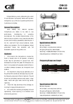
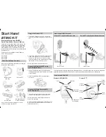
Figure 3 Location of the microphone opening on the new microphone

2.  Open the door.

3.  From the front of the door, insert the multimeter probe through the door’s microphone 

opening.

4.  Carefully insert the tip of the multimeter probe into the microphone opening on the 

microphone.

Caution:

The microphone on the other side of the opening is very delicate. 
Permanent damage to the microphone can result if you force the tip of the 
multimeter probe too far into the microphone opening.

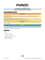
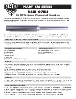
5.  Align the microphone so that the terminal for the wiring harness is on the bottom (see 

Figure 4).

Figure 4 Proper alignment of the of the microphone board

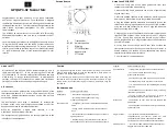
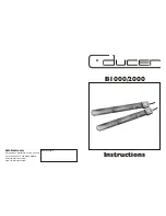
6.  Using the multimeter probe as a guide, move the microphone towards the door until the 

microphone attaches to the door.

Figure 5 Aligning the microphone with the microphone hole

Microphone 
opening

Adhesive

Terminal for the 
wiring harness
on bottom

Summary of Contents for MD-1243

Page 1: ...he following tools Screwdriver or a utility knife A multimeter probe To install the microphone you must perform the following steps A Shut down the unit and disconnect power B Remove the old microphone C Attach the new microphone to the door D Connect the wiring harness to the lobby controller board Details on how to perform these steps are in the following pages A Shut down the unit and disconnec...

Page 2: ...or The new microphone attaches to the inside of the door with double sided tape The microphone fits into an indentation in the door For ideal sound quality the opening on the flat side of the new microphone see Figure 3 must align with the microphone opening on the door Align and attach the new microphone to the door using a multimeter probe 1 Remove the sticker to expose the adhesive on the flat ...

Page 3: ...de of the opening is very delicate Permanent damage to the microphone can result if you force the tip of the multimeter probe too far into the microphone opening 5 Align the microphone so that the terminal for the wiring harness is on the bottom see Figure 4 Figure 4 Proper alignment of the of the microphone board 6 Using the multimeter probe as a guide move the microphone towards the door until t...

Page 4: ...in connector on the wiring harness to the 4 pin terminal on the lobby controller board as shown in Figure 6 2 If there is a jumper on JW11 remove it see Figure 6 3 Reconnect power to the unit and then turn it on Figure 6 Microphone wiring Speaker Connection White Microphone Connection Red Black Unused Unused JW11 open Sheild ...

Reviews: