background image


3   Operation 


3.1   FRS-111i User Interface 


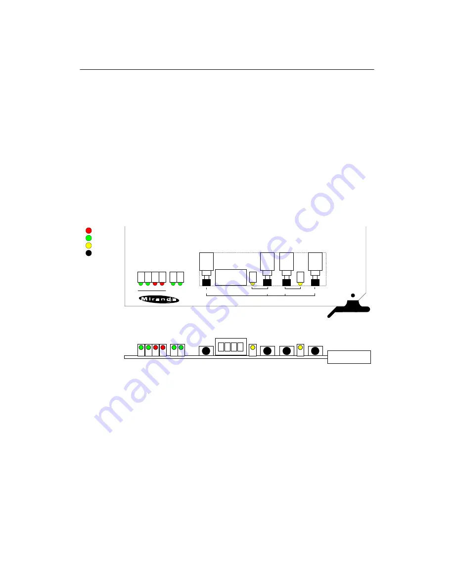
Figure 3.1 outlines the FRS-111i's user interface situated at the front end of the card. 
The interface components include, from left to right: 


  Line format status, error detection and reference status indicators 

  Menu controls pushbuttons and alphanumeric display 

  Video Freeze status indicator and pushbutton 

  Test signal selection pushbutton and status indicator 


For operating information on the above functions, refer to the rest of this section. 


Figure 3.1

   Front panel interface 


3.2   Line Format , Error Detection and Reference Status Indicators 


The following indicators provide information on the FRS-111i's line format status. 
Refer to Figure 3.1 for the correct indicator location. 


525


This LED turns on to indicate the FRS-111i has detected a 525-line format signal 
connected to 

4:2:2 IN


625


This LED turns on to indicate the FRS-111i has detected a 625-line format signal 
connected to 

4:2:2 IN

.


ERR


This LED lights up to indicate that the FRS-111i has detected an error on the 
serial digital video signal connected to 

4:2:2 IN

, and, when Input Freeze 

FRONT-TOP VIEW

Display

FRS-111i

FREEZE

TEST

SELECT

ESC

-

+

525 625 ERR EDH

FS

Red
Green
Yellow
Black

REF

INPUT

FRS-111i 4:2:2 FRAME SYNCHRONIZER

Summary of Contents for FRS-111i

Page 1: ...ion M264 9900 101 Copyright 2002 MirandaTechnologies Inc Specifications may be subject to change Printed in Canada August 2002 FRS 111i Miranda Technologies inc 3499 Douglas B Floreani St Laurent Québec Canada H4S 1Y6 Tel 514 333 1772 Fax 514 333 9828 www miranda com ...

Page 2: ...and holidays excluded All warranty exchange or loaner parts or products shall be shipped to the Buyer with a packing list clearly describing the items and stating the date of shipment Repaired parts or products will be shipped to the Buyer with a similar packing list In the case of exchange the defective products or parts must be returned to Miranda within fifteen 15 days from receipt by the custo...

Page 3: ...r Digital Devices This equipment complies with the requirements of EN55022 Class A Electromagnetic Emissions En 60555 2 3 Disturbance in Supply Systems and EN50082 1 Electromagnetic Immunity How to contact us Head Office Miranda Europe Miranda Asia Miranda Technologies Inc 222 226 Rue De Rosny Mita Nexus Bldg 2F 3499 Douglas B Floreani 93100 Montreuil 1 3 33 Mita Minato Ku St Laurent Montreal Que ...

Page 4: ...g Symphonie Connector Label 5 2 4 FRS 111i Electrical Installation 6 3 Operation 8 3 1 FRS 111i User Interface 8 3 2 Line Format Status Error Detection and Reference Stauts Indicators 8 3 3 Using the Menu 9 3 4 Timing Adjustments 11 3 4 1 Frame Phasing 11 3 4 2 Vertical Timing Delay 11 3 4 3 Horizontal Timing Delay 12 3 5 Ancillary Data Blanking Functions 12 3 5 1 HANC Blanking 12 3 5 2 VANC Blank...

Page 5: ...nked according to user selection Vertical interval data is buffered through blanked or processed on a line by line basis according to user selection An internal color bar generator further enhances the FRS 111i s functionality All outputs conform to the SMPTE 259M standard The easy to use microprocessor based user interface simplifies user selections and allows precise adjustments of the parameter...

Page 6: ...lications 1 3 1 Hot Switching Some applications or studio setups may require that the input 4 2 2 signal to the FRS 111i be switched between two or more synchronous sources Since these synchronous sources are generally not in phase with respect to each other unpleasant visual effects may occur when switching from source A to a different time position in source B Also some break before make switche...

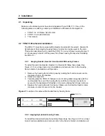
Page 7: ...uartet M follow these steps See Figure 2 1 For a closer look at card installation and removal refer to the housing frame s Guide to Installation and Operation 1 Remove the housing frame s front panel by rotating the thumb screws counter clockwise Pull on the handles 2 Select an empty slot 3 Carefully place the FRS 111i between a set of card guides and gently push the card towards the rear of the h...

Page 8: ...is card into Solo follow these steps For a closer look at card installation and removal refer to the housing frame s Guide to Installation and Operation 1 In order to remove the housing frame s front panel gently pull on it 2 Carefully place the FRS 111i between the card guides and gently push the card towards the rear of the housing frame until the card s edge connector is secured to the backplan...

Page 9: ...in this example 2 3 2 imaging Symphonie Connector Label To install the Symphonie label follow these steps while referring to Figure 2 4 1 On Symphonie s rear panel locate the appropriate connectors 2 Carefully apply the label to the connectors making sure the label s text is read from top to bottom Figure 2 4 Symphonie rear panel label installation ...

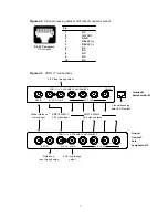
Page 10: ... 111i provides a loop through output of the studio reference signal Make sure to terminate this output with a 75 Ω terminator when it is not being used A valid analog composite reference signal will turn on the REF indicator located on the module s front end figure 3 1 The reference signal must be NTSC for 60 Hz sources and PAL for 50 Hz sources If there exists a line format mismatch between the r...

Page 11: ...2 2 video input Studio reference or black input Reference loop through output 4 2 2 loop through output FRS 111i 4 2 2 FRAME SYNCHRONIZER 1 2 Quartet Quartet C Solo Symphonie R C 4 2 2 loop through output Video processing delay GPI output IN 4 2 2 LOOP REF IN SMPTE 259M C 4 2 2 video outputs IN 4 2 2 LOOP FRS 111i 4 2 2 FRAME SYNCHRONIZER REF IN 1 2 DELAY Quartet M Symphonie R M 4 3 4 3 4 2 2 OUT ...

Page 12: ...ace 3 2 Line Format Error Detection and Reference Status Indicators The following indicators provide information on the FRS 111i s line format status Refer to Figure 3 1 for the correct indicator location 525 This LED turns on to indicate the FRS 111i has detected a 525 line format signal connected to 4 2 2 IN 625 This LED turns on to indicate the FRS 111i has detected a 625 line format signal con...

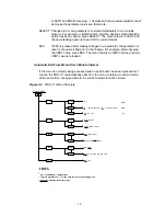
Page 13: ...so blink when the FRS 111i performs an automatic freeze caused by a loss of input or continuous input errors TEST This LED turns on when the internal test pattern is enabled 3 3 Using the Menu Most FRS 111i parameters are accessed and changed via an easy to use menu The flow chart of Figure 3 2 outlines the entire FRS 111i menu path The menu consists of 4 major functions timing ancillary data blan...

Page 14: ...ue is reloaded Automatic Exit From Menu After 1 Minute Interval If the menu is currently being accessed and no push button has been pressed for 1 minute the FRS 111i automatically exits from the menu returning to normal mode At the same time changes made to the current parameter will be stored Figure 3 2 FRS 111i Menu Structure UP and DOWN pushbuttons Terms in parentheses are the units for the cor...

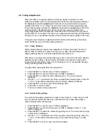
Page 15: ...e frame phasing adjustment adds a delay in frame increments between the input and output video Frame Delay Frame Buffer mode A zero phasing H V is not possible because of the processing delay of the card To adjust frame phasing perform the steps below 1 Press SELECT to enter the menu TIMG is displayed 2 Press SELECT to enter the Timing menu FRAM is displayed 3 Press SELECT to enable the frame phas...

Page 16: ... mode press ESC 3 5 Ancillary Data Blanking Functions 3 5 1 HANC Blanking Incoming horizontal ancillary data can be entirely blanked or can pass to the digital video output Within the HANC Blanking menu are two available options for HANC blanking PASS All incoming HANC data is allowed to pass through to the output BLNK All incoming VANC data is blanked To change VANC blanking setting follow these ...

Page 17: ...ess ESC 3 6 Freeze Functions The FRS 111i has a manual freeze pushbutton situated on the front edge of the module see figure 3 1 Front Panel Interface that allows a user to freeze grab a video image An automatic freeze function is also available and is able to handle a live hot switch on a pre selected video input 3 6 1 Automatic Freeze Mode The FRS 111i can automatically freeze the output image t...

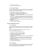
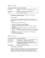
Page 18: ... 5 Use the or push button to choose the desired Freeze Type setting Press the and push buttons simultaneously to set Freeze Type to FRM default setting 6 Press SELECT to store the new Freeze Type setting TYPE is displayed 7 Press ESC to return to FRZE 8 To return to normal mode press ESC Table 3 2 Freeze types Freeze type selection Freeze type description FLD 1 field 1 FLD 2 field 2 Displays field...

Page 19: ...uts to their original values programmed during manufacturing To perform a factory reset follow these steps 1 Press SELECT to enter the menu TIMG is displayed 2 Press the push button until FACT is displayed 3 Press SELECT to enable the Factory Rest menu NO is displayed 4 Press the push button to display YES 5 Press SELECT to reset all parameter values to factory values for the current video format ...

Page 20: ... p Composite Sync Return Loss 35 dB up to 5 75 MHz DIGITAL OUTPUT Signal 2 4 2 2 SMPTE 259M C 270 Mbps Return Loss 15 dB up to 270 MHz Jitter Wideband 0 2 UI 0 74ns p p Delay Tracking Miranda video audio tracking signal PROCESSING PERFORMANCE DIGITAL Signal Path 10 bits Processing Delay 13 µs in delay mode 2 lines min in frame sync mode MISCELLANEOUS Test Signal 75 color bars 100 color bars black ...

Page 21: ...17 ...

Reviews: