GUIDE TO INSTALLATION AND OPERATION
CPU-ETH2 |
3
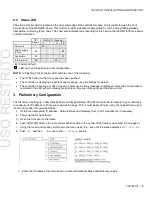
2.3 Status LED
The status monitor LED is located on the front card-edge of the controller module, and is visible through the front
access door of the DENSITÉ frame. This multi-color LED indicates module status by color, and by flashing/steady
illumination, according to the chart. The chart also indicates fault reporting for this card on the DENSITÉ frame’s serial
and GPI interfaces.
GPI
Report
COLOR (F=flashing)
G
Y
R
FR
No errors
Power supply
failure
Fan failure
Internal error
: Factory default.
: LED color and reporting not user configurable
NOTE:
A “Flashing Yellow” Status LED indicates one of the following:
•
The CTRL button on the front panel has been pushed.
•
The controller is displaying a spontaneous message – see the display for details.
•
The controller is booting up, after a reset or power up. A status message is displayed. Once the boot process is
completed, the LED will go to steady green unless there are other errors per the above chart.
3 Preliminary Configuration
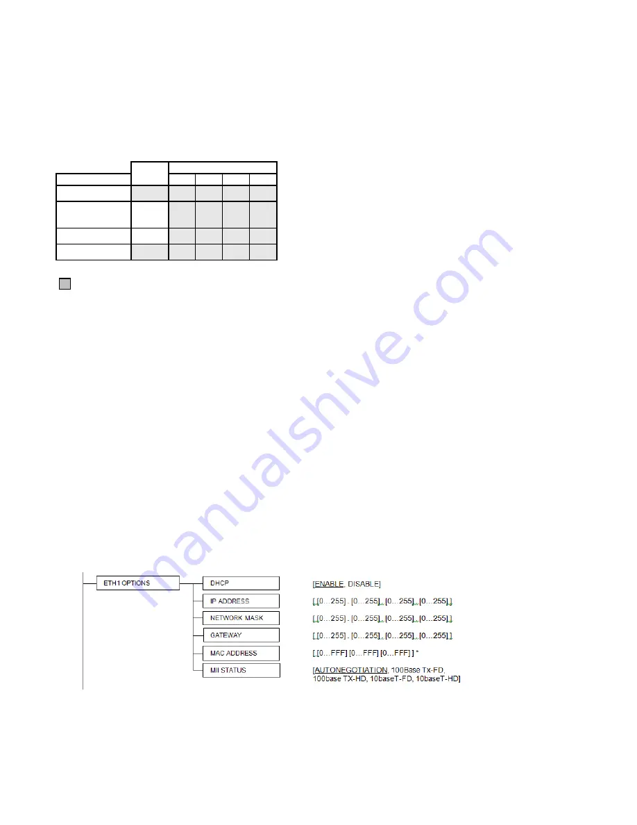
The first step in setting up a new Densité frame and its associated CPU-ETH2 controller to operate in your network is
to configure its IP address to fit into your network structure. This is most easily done by using the onboard menu and
local control panel. Proceed as follows:
1. Obtain the appropriate IP address, Network Mask and Gateway from your IT department, if necessary.
2. Power up the Densité frame.
3. Open the front door to the frame.
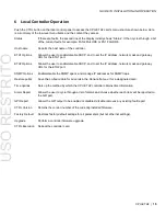
4. Push CONTROLLER on the local control panel located in the center of the frame (see section 2.2 on page 2)
5.
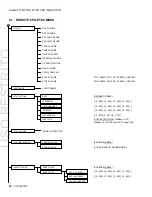
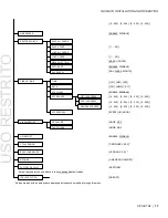
Using the local control panel, scroll down the menu using the – key until the screen displays
ETH1 OPTIONS
6. Push
SEL
and then
–
to move to the
IP ADDRESS
section
7. Enter the IP address, then scroll down to enter the Network Mask and Gateway values.
USO
RESTRITO


