background image

Assembly step 8

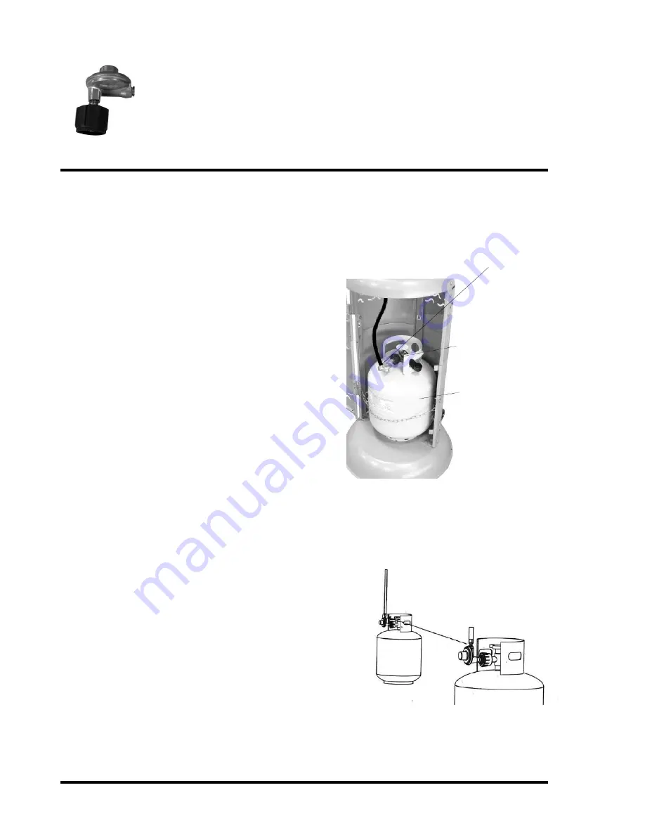
Regulator

Check for Leak

Your patio heater has been checked at

all factory connections for leakage. To

check the connection at the gas

hose/regulator/cylinder

1.

Make leakage solution by mixing 

50% water with 50% liquid dish soap.

2.

Brush several drops of the solution onto the gas 

hose/regulator/cylinder and hose connection

3.

Turn on the gas cylinder valve. Inspect the 

connections and look for bubbles

4

. If no bubbles appear the connection is safe

5.

If bubbles appear there is leakage, loosen and 

re-tighten this connection. If it still leaks,

please contact customer service on [email protected] 

or (678) 534 2876

Note:

The Cylinder must be positioned as shown in

the patio heater cylinder chamber to provide vapour
withdrawal.

Page 10

Points for leak testing

Hose / Regulator

Regulator / Cylinder

Connect the lantern hose to the regulator hose and secure tightly with

adjustable wrenches. Then attach the regulator to the cylinder, turn

clockwise to tighten it securely. Place cylinder in position as shown.

Connect

securely with

adjustable

wrenches

Screw regulator

onto gas 

cylinder

Position 

gas cylinder

inside cylinder

chamber 

as shown

securing 

with chain.

Summary of Contents for HDMIRAGE10

Page 1: ...use gasoline or other flammable vapors and liquids in the vicinity of this or any other appliance An LP cylinder not connected for use shall not be stored in the vicinity of any other appliance WARNI...

Page 2: ...1 Base 1 7 Lower Support Pole 1 2 Upper Lower Cylinder Chamber Supports A B and C 3 8 Upper Support Pole 1 3 Cylinder Chamber Door 1 9 Lantern 1 4 Cylinder Chamber Wall 1 10 Parasol Side Panels 6 5 Cy...

Page 3: ...lay out all nuts and bolts and check lengths before assembly It is recommended that the carton is cut open and spread out on the floor and used as a protective surface during assembly Refer to the ass...

Page 4: ...step 1 Base x 1 Cylinder chamber supports Base Upper Lower Cylinder Chamber Supports A B C Fix the cylinder chamber supports A B C to corresponding location on the base with 6 M6 bolts Ref C Page 3 M...

Page 5: ...y step 2 Lower Support Pole M6x12 Dome Hex Bolt C M6 Nut A M6x12 Bolt Cylinder chamber supports Fix lower support pole to cylinder chamber supports as shown using 6 M6 bolts Ref C and 6 M6 nuts Ref A...

Page 6: ...linder Chamber Wall Cylinder Chamber Wall Cylinder Chamber Supports M6Nut A Fit the cylinder chamber wall to the cylinder chamber supports using 6 dome head bolts Ref B and 6 M6 nuts Ref A Page 5 M6x1...

Page 7: ...Assembly step 4 Cylinder Chamber door Cylinder Chamber door Hinges Hang door on hinges Ensure correct alignment and tighten bolts securely Page 6...

Page 8: ...Cylinder Chamber Top M6 x 10 Dome Bolt B Cylinder Chamber Top Fit cylinder chamber top onto cylinder chamber support legs using 3 dome head bolts Ref B and M6 nuts Ref A Page 7 M6 Nut A M6x10 Dome He...

Page 9: ...Assembly step 6 M6x12 Dome Hex Bolts Page 8 Upper Support Pole Fit upper support pole to lower suport pole using 3 x m6x12 dome hex bolts Ref C M6 x 12 Dome Hex Bolt C...

Page 10: ...Assembly step 7 M6x12 Dome Hex Bolts Page 9 Lantern 1 Feed the lantern hose down the support pole and secure lantern to support pole using 4 M6x12 Dome Hex Bolts Ref C M6 x 12 Dome Hex Bolt C 1...

Page 11: ...pear there is leakage loosen and re tighten this connection If it still leaks please contact customer service on info uig biz or 678 534 2876 Note The Cylinder must be positioned as shown in the patio...

Page 12: ...tor handle Assembly step 9 Page 11 Retaining Pin Remove R clip and retaining pin Heat focus reflector bracket Reflector handle R Clip 1 2 3 Fit reflector handle Secure with retaining pin and R clip Re...

Page 13: ...s together overlapping as shown with 18 dome head bolts and nuts B A fix the top panel to the top of assembled side panels Tighten all nuts Fix assembled parasol onto top of Parabolic Reflector Bracke...

Page 14: ...urfaces with recommended cleaning agents if necessary An appliance may be installed with shelter no more inclusive than a With walls on all sides but with no overhead cover b Within a partial enclosur...

Page 15: ...r propane gas NEVER use an adjustable regulator with this appliance Please consult your gas dealer for the most suitable gas bottles for your regulator Siting Instructions This appliance is for OUTDOO...

Page 16: ...to position Turn the gas off and disconnect at the cylinder when not in use Flame Characteristic The flame pattern at the burner mesh should be visually checked whenever the heater is operated Normall...

Page 17: ...flammable structure or surface NEVER operate the heater with the top half covered burner head reflector etc DO NOT leave this product unattended when in use Always keep the cylinder level and vertical...

Page 18: ...ults from alteration product abuse or product misuse whether performed by a contractor service company or consumer We will not be responsible for labor charges and or damage incurred in installation r...

Reviews: