1
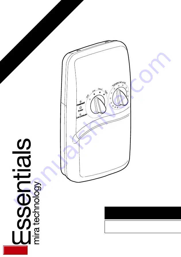
7.5, 8.5 and 9.5 kW
INSTRUCTION MANUAL
ELECTRIC SHOWER
THESE INSTRUCTIONS ARE TO BE LEFT WITH THE USER
back
Page 1: ...1 7 5 8 5 and 9 5 kW INSTRUCTION MANUAL ELECTRIC SHOWER THESE INSTRUCTIONS ARE TO BE LEFT WITH THE USER back ...
Page 2: ...Contents Checklist 6 Dimensions 7 Wiring Diagram 8 Specifications 9 Installation Requirements 9 Installation 14 Commissioning 18 Operation 19 Maintenance 23 Fault Diagnosis 25 Spare Parts 30 Accessories 30 Guarantee Customer Care Policy and How to contact us Back cover ...
Page 3: ...AC heater with an adjustable spray handset with three different spray actions start force and soothe Individual lights indicate POWER LOW PRESSURE and OVERHEAT Supplied complete with flexible hose adjustable clamp bracket assembly slide bar and supports and hose retaining ring Available in white chrome finish Essentials 8 5 A 8 5 kW 240 V AC 7 8 kW 230 V AC heater with an adjustable spray handset ...
Page 4: ... exposed to freezing conditions 7 DO NOT fit any form of outlet flow control as the outlet acts as a vent for the tank body Only Caradon Plumbing Solutions recommended outlet fittings should be used 8 There are no user serviceable components beneath the cover of the appliance Only a competent tradesperson should remove the cover 9 If any of the following conditions occur isolate the electricity an...
Page 5: ...ur electricity supply company to ensure that the electricity supply is adequate for the purpose 6 The plumbing installation must comply with the requirements of UK Water Regulations Bye laws Scotland Building Regulations or any particular regulations and practices specified by the local water company or water undertakers The installation should be carried out by a plumber or contractor who is regi...
Page 6: ...elf with the part names and to confirm that the parts are included 2 Documentation 1 x Instruction Manual 1 x Guarantee Card Section Pack Contents Checklist 1 Essentials 7 5 8 5 or 9 5 kW 1 x Essentials 7 5 8 5 or 9 5 3 x Fixing Screws 3 x Wall Plugs ...
Page 7: ...7 Section Dimensions 200 mm 83 mm 345 mm ...
Page 8: ...ACITY 3 mm CONTACT SEPARATION GREEN YELLOW BROWN 220 240V ACONLY HEATER TANK BLUE L E GREEN 61A BLUE 58 BLUE 59A GREEN 60 C C1 A A2 A1 B B1 BROWN 59A SWITCH ASSEMBLY NEON ASSEMBLY RED 57 THERMAL SWITCH ORANGE 56 BROWN 53 RED 54 N RED 59A BROWN 57 BROWN 55 PURPLE 59A ...
Page 9: ...tained inlet head of water of 8 metres the vertical distance from the base of the cold water storage cistern to the shower fitting handset To reduce pressure losses and fluctuations the cistern fed water supply must be independent from other supply draw offs and should avoid long horizontal pipe runs and use swept bends rather than 90 elbows The appliance may be installed with a shower pump to inc...
Page 10: ...ver it is advisable to seal around the incoming mains fed supply to prevent water ingress into the wall 9 Do not install the appliance in a position where it may become frozen The shower unit must not be fitted where it may be exposed to freezing conditions The shower unit must not be used if suspected of being frozen 10 We recommend that a non restrictive free flowing isolating valve is fitted in...
Page 11: ...inlet supply to the appliance cause a pressure build up which could exceed the maximum static inlet pressure for the appliance 16 Water flow can be obtained without the electrical power being connected This allows the plumbing connections to be tested prior to final connection of the electrical supply 17 Avoid layouts where the shower hose will be sharply kinked This may reduce the life of the hos...
Page 12: ... provided by this unit use the shortest possible cable route from the consumer unit to the shower It is also necessary to satisfy the disconnection time and thermal constraints which mean that for any given combination of current demand voltage drop and cable size there is a maximum permissible length of circuit As a guide only the following maximum permissible lengths are given for 6 mm2 cable pr...
Page 13: ...e live and neutral conductors as this will prevent them from entering the terminal block 8 DO NOT exert strain on the terminal block 9 DO NOT turn on the electrical supply until the plumbing has been completed Plumbing and Electrical Schematic Diagram ...
Page 14: ...e wall It is recommended to use a soldered elbow 1 6 The inlet connector assembly is configured to suit a falling supply To change the configuration to suit a rising supply refer to Figure 2 remove the inlet strainer and compression nut refit the inlet connector and compression nut in the opposite ends 1 7 Removeas appropriatethethinnedcaseareas tosuit thesuppliesenteringthe product 1 8 Thoroughly...
Page 15: ...ials shower must be fitted onto a finished flat and even wall surface small pillars moulded on to the back of the case allow air circulation Fixing Screw Inlet Connector Assembly Configuration For A Rising Supply Inlet Connector Assembly Configuration For A Falling Supply Inlet Connector Assembly Inlet Strainer Inlet Connector Assembly Inlet Strainer Make sure that the back inlet does not go into ...
Page 16: ...s of the live and neutral conductors or strain the wires to the terminal block form a loop as shown 1 15 Fit an earth sleeve to the earth conductor Connect the conductors firmly into theterminalblock Makesurethatthebarecoresofeachconductoraresecurely trapped within each conductor clamp L Redwire N Black wire E Yellow Greensleevedwire 1 16 Re tighten the terminal block screws 1 17 If necessary fit ...
Page 17: ...sitioned tofitontothespindlesallowing the cover to fit properly Fit and tighten the three cover retaining screws 1 19 Fit the shower fittings Refer to separate instructions Overheat Overheat Power Low pressure Low pressure Temp ratu e e r S t o p Low Med H i g h Spindle Positions when replacing Cover Figure 4 D Spindle ...
Page 18: ...low will be reduced and the temperature will remain cool this shows that the flow regulator assembly is operating correctly Return the knob to full flow 7 Turn the left hand knob to the Med position The temperature of the water should rise slightly Allow a few seconds for the warm water to reach the handset this shows that the half power setting is operating correctly 8 High position The temperatu...
Page 19: ...ll require the Temperature knob to be adjusted as necessary 5 The appliance requires a minimum pressure of 0 8 bar to operate At pressures above 0 8 bar the appliance will minimise the temperature fluctuations caused when other draw off points are used If the flow rate drops below an acceptable value the appliance will turn the heater elements off resulting in a cold shower The Low pressure neon o...
Page 20: ...20 SelectShower TemperatureBy RotatingClockwiseAs Necessary EssentialsControls Figure 6 ...
Page 21: ... setting with an incoming water supply at10 Candashoweringtemperatureat42 C thetemperatureriseis32 C Theflowrate is therefore 4 l min a These curves are for the specified outputs at 240V b Allapplianceheatingelementshaveamanufacturingtolerance Thusflow rates can be above or below those indicated c The left hand scale is temperature rise Temperature rise Showering temperature minus the incoming col...
Page 22: ...owly to adjust temperature Allow 10 15 seconds for the adjusted temperature to reach the handset The control knob operates through approximately of a turn from cold to hot Clockwise rotation will give warmer water with less flow Anticlockwise rotation will give cooler water with more flow Note Should the product alternate Hot Cold Adjust the right hand control knob anti clockwise to reduce the tem...
Page 23: ...ns 5 Refit the components in reverse order Maintenance Cleaning Many household cleaners contain abrasives and chemical substances and should not be used for cleaning plated or plastic fittings These finishes should be cleaned with a mild washing up detergent or soap solution and then wiped dry using a soft cloth General Read the section Important Safety Information first Providingtheshowerhasbeenc...
Page 24: ...over and the relief valve assembly and will fall out when the cover is removed 2 Use suitable pliers to remove the relief valve assembly Do not remove the O seal 3 Moisten the rubber ball and insert it into the inner end of the relief valve assembly 4 Refit the components in reverse order Refer to the INSTALLATION section of this guide or the label inside the cover for the correct alignment of spi...
Page 25: ...e clean Refer to Maintenance in the Shower Fittings Instruction Manual Incoming water supply stop valves or appliance isolating valve turned down or off Low pressure light illuminated Turn stop isolating valve fully to fully on position HoseorHandsetblocked Clearblockageorrenew Appliancefailsto produce hot water in anyswitchposition Electricalsupplyisolatedat doublepoleswitch the pullcord Switchon...
Page 26: ...ppliance isolating valve turned fully on If fault still persists contact your installer Unable to select a cool enoughshower duringsummermonths Due to the rise in water mainssupplytemperature the power rating may be too high Turn the left hand knob to LOW settingandre adjust temperatureknobuntilsuitable temperatureisachieved Operationof temperatureknobhas little or no effect on watertemperature Re...
Page 27: ...olved WARNING There are no user serviceable components beneath the cover of the appliance Only a competent tradesperson should remove the cover Key light illuminated A POWER indicator B LOW PRESSURE indicator C OVERHEAT indicator Malfunction A Cause Remedy C B No water or very low flow rate Handsetsprayplate assemblyblocked Remove and clean refer to Maintenance in the Instruction Manual for the sh...
Page 28: ...erature Turn the right hand knob sufficientlyanticlockwise to increase the water flowandprevent operation of the thermal switch DONOTtamper with the thermal switch Appliancefailsto producehotwater in any switch position Electricalsupplyisolatedat doublepoleswitch the pullcord Switchon Fuse blown orMCB RCD tripped indicating an electrical fault e g heater tankelementfailure Correct the fault and re...
Page 29: ...is blocked or the unit is frozen When the relief valveoperatesasmall rubber ball is ejected Reset the relief valve assembly refer to Maintenance Relief ValveResetting Renew the pilot valve Contactlocalwater authority undertaker Checkwatersupply staticpressure Note Staticpressure may fall below 0 5 bar whenotherappliances areoperatede g dishwasher washing machineetc Pilot valve faulty Supplypressur...
Page 30: ... Assembly 7 5 kW 240 V AC 6 85 kW 230 V AC 43194 Heater Tank Assembly 8 5 kW 240 V AC 7 8 kW 230 V AC 43195 Heater Tank Assembly 9 5 kW 240 V AC 8 7 kW 230 V AC 43196 Inlet Connector Assembly 43197 ServiceTunnel 43199 Neon Assembly 87228 Microswitch C O 3 pin Accessories DCV H Outlet double check valve DCV H Anoutletdoublecheckvalve designedtopreventthebackfloworbacksiphonage ofpotentiallycontamin...
Page 31: ...nnectors must be assembled back to back onto terminals of microswitches A minimum gap of 4 mm must be maintained between the connectors after assembly 431 96 419 82 419 86 431 76 431 75 417 46 872 28 431 93 431 94 431 95 147 50 431 92 419 88 431 97 431 87 431 86 431 99 ...
Page 32: ... Phone Dublin 01 4591344 Monday to Friday 9am 5pm By Fax Dublin 01 4592329 24 Hours By Post Modern Plant Ltd Otter House Naas Road Clondalkin Dublin 22 Eire Guarantee Caradon Plumbing Solutions guarantee this product against any defect of materials or workmanship for one yearfromthedateofpurchase providedthattheproduct has been installed correctly and used and maintained in accordance with the ins...