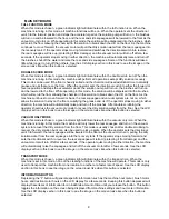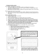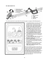
7. Stepping on the
Accelerator Pedal
turns on the
Transport,
Brushes, Water Flow, Vacuum
and
lowers the
Rear Squeegee
accordingly to the Mode selected. If the operator steps on the
accelerator pedal before, or turns the key switch “ON” at the same time, the machine will not move
as a safety precaution. Simply remove your foot off the pedal and step on the pedal again to drive
the machine. Please refer to the
Main Keyboard section
of this manual for a complete description of
the functions.
8. When
Reverse
is selected on the Directional Switch, the
Back-up Alarm
will be activated and the
Rear Squeegee
automatically is raised when you step on the accelerator pedal. However, the
Scrub brushes will continue to rotate and solution will continue to flow.
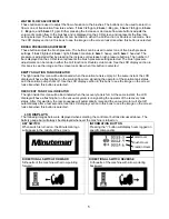
9. Start scrubbing by driving the machine forward in a straight line at 3/4 speed and overlap each path
by 2 to 3 inches. Adjust your speed; brush pressure and solution flow according to the condition of
the floor.
CAUTION!
To avoid any damage to the floor, keep the machine moving when the brushes are turned on.
10. When scrubbing, check behind the machine occasionally to see that all the dirty water is being
picked up. If streaking occurs, your
Water Flow
setting may be
too high
, the
Recovery Tank
may
be
full
, the
Squeegee hose
may be
clogged
, or the
Rear Squeegee
may require some
adjustment.
11. Make the necessary adjustments on the
Rear and Side Squeegees
if streaking occurs both in
straight paths and in turns. Pleas refer to the
Rear Squeegee
and
Side Squeegee
section of this
manual before making any adjustments.
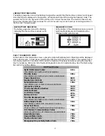
12. In cases where the floors are extremely soiled and dirty, the
Double Scrub
mode may be needed.
As described in the
Main Keyboard section
of this manual, this mode allows the operator to be able
to scrub an area without recovering the cleaning solution with the rear squeegee in the raised
position (no vacuum) to allow the cleaning solution a longer time to loosen dirt. A final pass on the
same area is made with the mode switched over to either
Full Function
or
Vacuum Only
mode to
recover the dirty water.
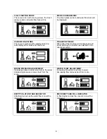
13.
The recovery tank has two safeguards for overflow protection to guard against water from entering
the vacuum system when the recovery tank is full. When the
indicator light
is lit up in the
Keyboard
,
the
Vacuum icon
in the
LCD Screen
will be
flashing
(see the
LCD Display
section of this manual)
.
The vacuum will stay ON for 15 seconds and then shut-off automatically. A ball float shut-off system
has also been integrated into the Recovery Tank. When the dirty water reaches a certain level, the
ball gets suctioned into the vacuum manifold and blocks the airflow thus, preventing the machine
from picking up more liquid. When this happens, the operator is then required to stop scrubbing and
empty the recovery tank.
14. To stop scrubbing, select the
Transport mode
. This will automatically stop the
Solution Flow
,
raise the
Scrub deck
, and raise the
Rear squeegee
(there is a 15 second delay for the vacuum
motor).
15. Drive the SCV to a designated dirty water disposal area and empty the Recovery tank. To empty,
remove the
Drain hose
from its storage hanger. Unscrew the plug and hold the hose end above
the water level in the tank to avoid sudden, uncontrolled flow of dirty water. With the plug
completely off, carefully direct the water flow to the desired drain. Reinsert the plug and tighten and
return to its storage hanger.
16. The recovery tank should be rinsed out to remove solids in the tank. Open the
Cleanout cap
to
remove the
Stopper
plug.
Tilt the recovery tank (similar to accessing the batteries) and clean the
sludge that has settled in the sump area by either back flushing or by scraping it out. Be sure to
tightly secure the
Stopper
plug
and cleanout cap before continuing to operate the scrubber.
17. Refill the solution tank and continue scrubbing until the job is done or when the machine runs out of
power.
18. The
battery gauge bar icon
will flash to signal the operator that the machine is almost out of
power. Once this signal is displayed to the operator,
all functions will shut off
(brush will turn off and
the scrub deck will raise up, water flow will cease, the rear squeegee will raise up and the vacuum
motor will turn off) including the transport mode. The operator has to turn the
key switch OFF
and
then,
ON
to reset
the machine. The machine then will only have a few minutes left of reserve
power for a short
Vacuum only mode
to pick up remaining solution on the floor and
Transport
power
to drive to the battery recharging station.
18
Summary of Contents for SCV28
Page 1: ...SCV 28 32 RIDER SCRUBBER OPERATION SERVICE PARTS CARE ...
Page 3: ...3 ...
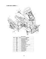
Page 31: ...EXPLODED VIEWS MAIN ASSEMBLY I 25 ...
Page 32: ...26 ...
Page 33: ...MAIN ASSEMBLY II 27 ...
Page 34: ...28 ...
Page 35: ...MAINFRAME ASSEMBLY I 29 ...
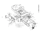
Page 36: ...MAINFRAME ASSEMBLY II 30 ...
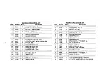
Page 37: ...31 ...
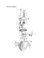
Page 38: ...FRONT DRIVE ASSEMBLY 32 ...
Page 39: ...33 ...
Page 40: ...STEERING ASSEMBLY 34 ...
Page 41: ...35 ...
Page 42: ...LCD HOUSING ASSEMBLY 36 ...
Page 43: ...SOLUTION TANK ASSEMBLY 37 ...
Page 44: ...38 ...
Page 45: ...ELECTRICAL PANEL ASSEMBLY 39 ...
Page 46: ...CONSOLE ASSEMBLY 40 ...
Page 47: ...RECOVERY TANK ASSEMBLY I 41 ...
Page 48: ...42 ...
Page 49: ...RECOVERY TANK II 43 ...
Page 50: ...DIVERTER ASSEMBLY 44 ...
Page 51: ...BATTERY BOX ASSEMBLY 45 ...
Page 52: ...PUMP ASSEMBLY 46 ...
Page 53: ...47 ...
Page 54: ...REAR AXLE ASSEMBLY 48 ...
Page 55: ...SQUEEGEE MECHANISM ASSEMBLY 49 ...
Page 56: ...REAR SQUEEGEE ASSEMBLY 28 50 ...
Page 57: ...51 ...
Page 58: ...REAR SQUEEGEE ASSEMBLY 32 52 ...
Page 59: ...53 ...
Page 60: ...28 CYLINDRICAL SCRUB DECK ASSEMBLY 54 ...
Page 61: ...55 ...
Page 62: ...28 DISC SCRUB DECK ASSEMBLY 56 ...
Page 63: ...57 ...
Page 64: ...32 CYLINDRICAL SCRUB DECK ASSEMBLY 58 ...
Page 65: ...59 ...
Page 66: ...32 DISC SCRUB DECK ASSEMBLY 60 ...
Page 67: ...61 ...
Page 68: ...CYLINDRICAL DECK AND SIDE SQUEEGEE MOUNTING 62 ...
Page 69: ...63 ...
Page 70: ...DISC SCRUBDECK AND SIDE SQUEEGEE MOUNTING 64 ...
Page 71: ...65 ...
Page 72: ...28 SIDE SQUEEGEE RIGHT SIDE 66 ...
Page 73: ...28 SIDE SQUEEGEE LEFT SIDE 67 ...
Page 74: ...32 SIDE SQUEEGEE RIGHT SIDE 68 ...
Page 75: ...32 SIDE SQUEEGEE LEFT SIDE 69 ...
Page 76: ...OFF AISLE WAND ASSEMBLY 70 ...
Page 77: ...71 ...
Page 78: ...PLUMBING DIAGRAM 72 ...
Page 79: ...WIRING DIAGRAMS POWER WIRING 73 ...
Page 80: ...INPUTS TO CONTROLLER 74 ...
Page 81: ...OUTPUTS FROM CONTROLLER 75 ...
Page 82: ...KEYBOARD WIRING 76 ...
Page 83: ...MACHINE SCHEMATIC 77 ...
Page 84: ...1 03 78 ...

