background image

4

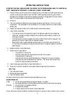
OPERATING INSTRUCTIONS

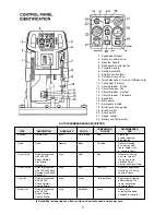
BEFORE STATING, FAMILIARIZE YOURSELF WITHTHE MACHINE AND ITS CONTROLS
(SEE “MACHINE OVERVIEW” & CONTROL PANEL DIAGRAMS)

1. Filling: Fill the solution tank with the desired amount of water and add liquid cleaning

solution to the proper dilution ratio. DO NOT USE powdered cleaning chemicals.
Powders are unlikely to dissolve thoroughly, resulting in clogging the in-line solution
filter.  This can reduce or stop water flow to the brush.

2. Close lid.
3. Turn on machine by lifting the red emergency disconnect button (17) so it is in the

up position.  Turn keyswitch (15) clockwise to “on” position and turn on main power
switch (16).

4. Adjust main speed control (21) to full counter-clockwise position.
5. Lower brush assembly.

-

To lower the brush, first push the pedal (10) slightly outward on the machine
(unlock it), and then release it slowly or by pressing “brush down” switch (19)
on Deluxe models.

-

To lift the brush, press the pedal (10) down until lift mechanism engages or by
pressing ”brush up” switch (19) on Deluxe models.

-

Brush will come on automatically when brush in on the floor and “forward” (5)
or “reverse” (3) handles are squeezed and remain on approximately 5 seconds
after release.

6. Adjust solution control feed lever.
7. Select vacuum operations:

-

“Vacuum On” mode (23)
Vacuum will remain on until switched to the “off” position

-

“Vacuum Auto” mode (23) –
Vacuum will come on automatically when “forward” or “reverse” handle
is squeezed, and scrubhead is on the floor.  The brush and vacuum will
remain on approximately 5 minutes.

8. Lower squeegee assembly by lowering handle (1).
9. Squeeze “forward” handle (5) and adjust forward speed (21) as desired.

After Use:

1. Turn off solution feed.
2. Raise squeegee assembly.
3. Turn off vacuum motor.

Solution and recovery tanks should be emptied after every use.

MAINTENANCE:

Daily

1. Clean float assembly & squeegee blades.  Vac filter
2. Recharge batteries (check battery acid levels before and after charging).

Monthly

1. Check wear on squeegee blades.
2. Grease front wheels.
3. Grease pivot points on brush motor assembly.

Every 500 hours check condition of carbon brushes on vacuum motor and brush drive motor.

Summary of Contents for mc20001qp

Page 1: ...200X Traction Drive Deluxe Floor Scrubber Battery Model MC20001QP CE MC20002QP CE Revised 10 03 OPERATION SERVICE PARTS CARE ...

Page 2: ......

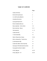
Page 3: ...ation Removal 6 Base Assembly Traction Drive 7 8 BaseAssembly Deluxe 9 10 TankAssembly 11 12 UpperAssembly 13 ConsoleAssembly 14 Motor Lift Assembly Deluxe 15 16 Motor Lift Assembly Traction Drive 17 ScrubheadAssembly 18 Dashboard Back Panel Assembly 19 Squeegee Lift Mechanism Assembly 20 SqueegeeAssembly Complete 21 Wiring Diagram 22 23 Wiring Diagram CE 24 25 ...

Page 4: ...rforming any maintenance procedures Store or park this machine on a level surface only These machines are designed for level floor operation only DO NOT OPERATE on ramps or inclines Battery acid can cause burns When working on or around batteries wear protective clothing and safety glasses Remove metal jewelry Do not laytools or metal objects on top of batteries This machine is not suitable for pi...

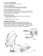
Page 5: ... not lay tools or metal objects on top of batteries BATTERY INSTALLATION 1 Raise tank assembly by gripping the front of the tank and lift the tank backward as shown in Fig 1 3 Install batteries as shown in Figure 2 CHARGING OF BATTERIES Charging of batteries generates explosive gases DO NOT CHARGE BATTERIES WHEN OPEN FLAMES OR SPARKS ARE PRESENT DO NOT SMOKE Make sure the charger is turned off bef...

Page 6: ...wn Black Aggressive stripping with 80 Grit and scrubbing tile Silicon Carbide floors unfinished Coarse Bristle concrete floors Strata Grit Nylon impregnated Long Dark Blue Black Heavy duty with 46 Grit stripping scrubbing Silicon Carbide unfinished concrete Coarse Bristle 1 Squeegee lift lever 2 Recovery dump hose 3 Reverse handle 4 Dashboard control panel 5 Forward handle 6 Safety bar switch 7 So...

Page 7: ...nism engages or by pressing brush up switch 19 on Deluxe models Brush will come on automatically when brush in on the floor and forward 5 or reverse 3 handles are squeezed and remain on approximately 5 seconds after release 6 Adjust solution control feed lever 7 Select vacuum operations Vacuum On mode 23 Vacuum will remain on until switched to the off position VacuumAuto mode 23 Vacuum will come o...

Page 8: ... enough raise the castor by turning the stem counter clockwise to adjust the castor height to allow more down pressure on the squeegee Repeat Step 2 6 Make sure that there is an even deflection on the entire length of the rear blade Adjust the castors and retighten the wing jam nuts to lock the castor setting in place 7 Pitch adjustment is necessary if the outer ends on the squeegee blade does not...

Page 9: ...e scrubhead shroud while lining up the center hex drive hub and pressing the brush up until the brush engages on the drive hub REMOVAL Traction Drive 1 Raise the scrubhead to the UP position by depressing the pedal A downward as shown on Fig 1 Deluxe Model 1 Raise the scrubhead to the UP position by pressing the switch BRUSH UP B switch as shown on Fig 2 until the scrubhead stops retracting upward...

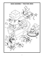
Page 10: ...7 BASE ASSEMBLY TRACTION DRIVE ...

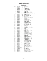
Page 11: ...1 Battery Liner 27 712565 5 SCR MC 1 4 20 x 62 SS 28 200145 1 Hinge 29 200146 1 Hinge Plate 30 711228 4 Bolt HH 5 16 18 x 3 4 31 711507 4 WSR Flat 37 x 1 12 x 06 32 200233 1 Bottom Cover 33 712822 5 SCR THMS 10 24 x 1 2 34 200235 1 Hose Nylobraid 17 50 35 450076 2 Crimp Clamp 185R SS 36 200155 1 Scrubhead Assy TD Deluxe 37 200186 1 Motor Cover 38 200302 1 Motor Lift Assy TD 39 712099PLT 2 Shoulder...

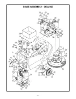
Page 12: ...9 BASE ASSEMBLY DELUXE ...

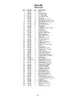
Page 13: ...2 SS 28 200145 1 Hinge 29 200146 1 Hinge Plate 30 711228 4 Bolt HH 5 16 18 x 3 4 31 711507 4 WSR Flat 37 x 1 12 x 06 32 200233 1 Bottom Cover 33 712822 5 SCR THMS 10 24 x 1 2 34 200235 1 Hose Nylobraid 17 50 35 450076 2 Crimp Clamp 185R SS 36 200155 1 Scrubhead Assy TD Deluxe 37 200186 1 Motor Cover 38 200290 1 Motor Lift Assy 39 712099PLT 2 Shoulder Bolt 1 2 x 50 40 711510 4 WSR Flat 50 x 1 38 x ...

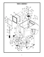
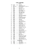
Page 14: ...11 TANK ASSEMBLY ...

Page 15: ...32 x 87 ST PL 25 200234 1 Solution Hose 26 130118 1 Solution Strainer 27 712540 3 SCR MC 10 24 x 375 SS 28 712574 1 CR Bolt SS 1 4 20 x 3 29 712667 2 Nut Hex 1 4 20 SS Nyloc 30 200321 1 Gasket Shut Off 31 712568 1 SCR MC 1 4 20 x 2 25 SS 32 832996 1 Terminal Block 2 Pole VDE 33 833316 1 Drain Plug 34 740225 1 Vac Motor 6515 13 24V 35 760245 2 Hose Clamp 62P24 36 760343 1 Tube Hose 24 32B 37 762384...

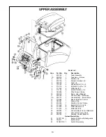
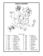
Page 16: ...rmed Hook 10 200176 1 Dump Hose Bracket 11 200180 1 Console Assy TD Deluxe 11A 200170 1 Console Assy Brush Drive 12 715284 1 Decal Solution Control 13 383367 1 Spring Clip 14 430053 1 Solution Control Cable 15 711228 6 Bolt HH 5 16 18 x 3 4 16 711545 6 WSR Helical 5 16 17 711575 6 WSR Flat 5 16 18 200032 1 Console Back Cover Weldment 19 450054 1 Vacuum Recovery Hose 20 200152 1 Solution Control Br...

Page 17: ...Stop RH 42 200040 1 Bail Stop LH 43 711160 8 Screw Hi Lo 10 x 5 8 PL 44 260210 1 Moisture Guard SCR 260TD Item Part No Qty Description 1 200104MCH 1 Console Machined 2 200134 1 Console Bracket Right 3 200135 1 Console Bracket Left 4 200181CTD 2 Handle Wire Coated 5 200295 1 Dashboard Assy TD DLX 6 712320 4 WSR Nylon 22 x 45 x 04 7 712540 8 SCR MC 10 24 x 37 SS 8 711575 6 WSR Flat 31 x 75 x 06 9 71...

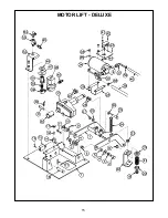
Page 18: ...15 MOTOR LIFT DELUXE ...

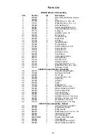
Page 19: ...5 16 x 1 75 26 711515 6 WSR Flat 406 x 81 x 063 27 711373 1 Nut Nyloc 1 4 20 200285 Pump Actuator Assembly 28 200174 1 Pump Mounting Bracket 29 712638 4 Nut Nyloc 10 24 SS 30 200248 1 Pivot Tube 31 831965 1 Clevis Pin 3 8 x 1 63 32 711808 1 Cotter Pin 33 743503 1 Actuator 34 833299 1 Pump 35 711505 4 WSR Flat 1 4 36 712532 4 SCR MC 10 24 x 1 SS 37 833325 2 Elbow 3 8 Barb x 1 4 NPT 38 450076 2 Crim...

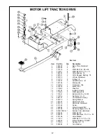
Page 20: ...14 740132 2 Insulator Glastic 15 711546 2 WSR Helical 3 8 16 713041 2 Bolt HH 3 8 16 x 3 4 5 17 711376 1 Nut Nyloc 1 2 13 18 260137 1 Compression Spring 19 200110 1 Spring Bracket 20 200149 1 Adjustment Rod 21 200116 1 Pedal Arm Weldment 22 210142 1 Pedal 23 740493 1 Water Solenoid 24V 24 200195 1 Reducing Nipple 3 8 x 1 4 25 809413MCH 1 Solution Valve Machined 26 829463 1 WSR Flat SS 27 828975 1 ...

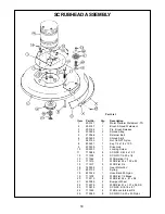
Page 21: ...35 1 Drive Hub 10 500033 1 Locking Screw 11 710986 4 SCR SC 3 8 16 x 1 00 12 711202 3 SCR MC 1 4 20 x 1 2 13 711544 3 WSR Helical 1 4 14 711519 1 WSR Flat 25 x 1 00 x 03 15 711517 3 WSR Flat 3 4 16 740209 1 Gear Motor 24V 17 833102 1 Spring 18 833325 1 Hose Barb 90 Nylon 19 711578 2 WSR Flat 1 2 Brass 20 712310 8 WSR Flat 52 x 87 x 06 21 430085 2 Bumper Wheel 22 712579 2 WSR Flat 31 x 1 37 x 06 SS...

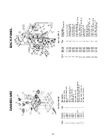
Page 22: ... Description 1 200124 1 Backpanel Weldment 2 3 711368 2 Wing Nut 1 4 20 4 740132 2 Insulator Glastic 5 740238 2 Circuit Breaker 18 6 740247 1 Circuit Breaker 30 7 742000 3 Diode Assembly 8 740549 1 Circuit Breaker 50 9 741037 1 5 Sec True Off Delay Timer 10 742403 1 Shunt Calibrated 11 743250 1 Wire Harness Lower Assy 12 788147 3 Solenoid 24VDC 13 833638 2 Brass Stud 14 711425 8 Whiz Nut 1 4 20 15...

Page 23: ...dment 14 711642 1 3 16 X 1 00 Roll Pin 15 711504 2 WSR Flat 1 4 SS Part List 200153 Item Part No Qty Description 1 200144 1 Spring Housing Weldment 2 200300 1 Yoke Weldment 3 210375 1 Swivel Pin 4 210391 2 Return Spring SS 5 210415 1 Clevis Pin 31 x 1 7 11 097 6 260041 4 Oilite Flange Bushing 7 710180 1 SCR MC 1 4 20 x 75 ST PL 8 711544 1 WSR Heliical 1 4 9 711519 1 WSR Flat 25 x 1 01 x 06 10 7118...

Page 24: ...op Bar 19 320308 1 Strap Front Clamp 320 20 383424 1 Mounting Bracket Right 21 383425 1 Mounting Bracket Left Item Part No Qty Description 22 710530 7 SCR MC 8 32 x 50 BR 23 711026 5 Nut Hex 8 32 Nyloc SS 24 711241 4 SCR Hex 3 8 16 x 75 ZP 25 711367 2 Nut Wing 3 8 16 ST PL 26 711504 4 WSR Flat 1 4 ID SS 27 711507 4 WSR Flat 37 x 1 12 x 06 28 711509 1 WSR Flat 1 2 54 x 1 08 x 087 29 711524 2 WSR Wa...

Page 25: ...22 WIRING DIAGRAMS ...

Page 26: ...23 200X TRACTION DRIVE AND DELUXE ...

Page 27: ...24 200X TRACTION DRIVE AND DELUXE ...

Page 28: ...25 CE 200X TRACTION DRIVE AND DELUXE ...

Page 29: ...26 CE 200X TRACTION DRIVE AND DELUXE ...

Page 30: ... All warranteed items become the sole property of Minuteman International Inc or its original manufacturer whichever the case may be Minuteman International Inc disclaims any implied warranty including the warranty of merchantability and the warranty of fitness for a particular purpose Minuteman International Inc assumes no responsibility for any special incidental or consequential damages This li...

Reviews: